
Image pickup device and image pickup method

a pickup device and pickup method technology, applied in the field of image pickup devices and image pickup methods, can solve the problems of large device scale and calculation number, inability to meet the requirements of low-cost device types, and difficulty in sufficiently reproducing the gradation of an intermediate area in the method, etc., and achieve the effect of simple control operation

Inactive Publication Date: 2011-10-18
SONY CORP
View PDF18 Cites 13 Cited by
  • Summary
  • Abstract
  • Description
  • Claims
  • Application Information

AI Technical Summary

Benefits of technology

The present invention provides an image pickup device and method that can generate an image that is suitable for a wide dynamic range of objects by a simple controlling operation. The device uses a combination of two images with different exposure times to estimate the dynamic range of the object. The dynamic range is calculated by a dynamic range calculating section and a base compression curve is interpolated between a location where the dynamic range is small and a location where it is large. The combined image is then compressed using the base compression curve and a histogram. The device is cost-effective and can be used in low-speed exposure conditions. The technical effect of the invention is to provide an image pickup device and method that can generate an image that is suitable for a wide dynamic range of objects by a simple controlling operation.

Problems solved by technology

Further, when an exposure ratio between the long-time exposure image and the short-time exposure image is very large, and the gradation changes continuously, it is difficult to sufficiently reproduce the gradation of an intermediate area in the method that uses two portions.
The method of performing a dynamic range compression at a smooth compression curve in which many output ranges are assigned to brightness areas having many distributions is an excellent method, but the scale of a device and the number of calculations are large.
Therefore, this method is not suitable for a low-cost device type.

Method used


Image

  • Image pickup device and image pickup method
  • Image pickup device and image pickup method
  • Image pickup device and image pickup method

Examples


Embodiment Construction

[0042]An embodiment of the present invention will hereunder be described in detail with reference to the drawings. The present invention is not limited to the following embodiment. It is obvious that modifications may be arbitrarily made without departing from the gist of the present invention.

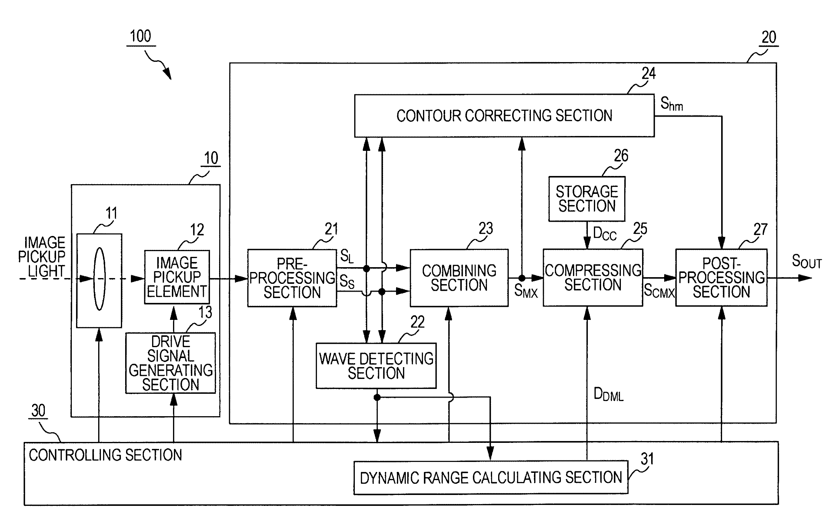
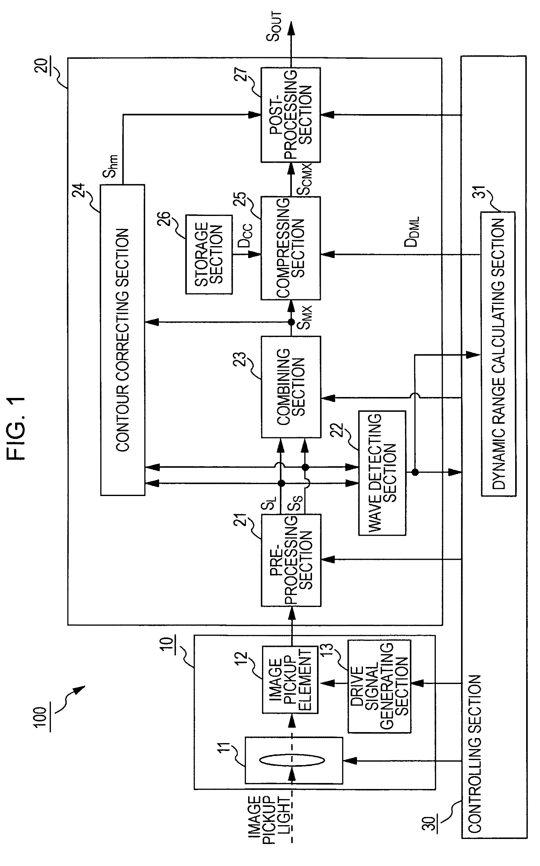
[0043]The present invention is applied to, for example, an image pickup device 100 having the structure shown in FIG. 1.

[0044]The image pickup device 100 includes an image pickup section 10 that picks up an object, a signal processing section 20 that processes an image signal obtained by the image pickup section 10, and a controlling section 30 that controls operations thereof.

[0045]The image pickup section 10 includes, for example, an image pickup optical system 11, an image pickup element 12, and a drive signal generating section 13. The image pickup optical system 11 includes optical components, such as a taking lens, an optical filter that removes undesired wavelengths, and a stop. The ima...


PUM


Abstract

An image pickup device includes an image pickup section that picks up a long-time exposure image and short-time exposure image; a combining section that combines the long-time exposure image and short-time exposure image with each other, to generate a combined image, the exposure images being combined on the basis of a ratio between the exposure time of the long-time exposure image and the exposure time of the short-time exposure image; a dynamic range calculating section that calculates an object dynamic range from the long-time exposure image, the exposure time of the long-time exposure image, the short-time exposure image, and the exposure time of the short-time exposure image; and a compressing section that, using base compression curve data, calculates a compression curve suitable for the object dynamic range, and generates a compressed image in accordance with the calculated compression curve.

Description

BACKGROUND OF THE INVENTION[0001]1. Field of the Invention[0002]The present invention relates to an image pickup device and an image pickup method for shooting an object in a wide dynamic range by combining images having two types of exposure times.[0003]2. Description of the Related Art[0004]In a related image pickup device using a solid-state image pickup element, such as a charge coupled device (CCD), a light quantity (exposure amount) input to the image pickup element is adjusted by a stop or on the basis of an electronic shutter speed. That is, when a bright scene is picked up, in order to prevent what is called overexposure (in which an output signal of the image pickup element is saturated) from occurring, the exposure amount is reduced. In contrast, for a dark scene, in order to prevent what is called underexposure from occurring, the exposure amount is adjusted to a large exposure amount.[0005]However, when a scene 5 having a large difference in brightness is picked up (tha...

Claims


Application Information

Patent Timeline
Patent Type & Authority Patents(United States)
IPC IPC(8): H04N5/202H04N5/235H04N23/76
CPCG06T5/009G06T5/40G06T5/50H04N5/35581G06T2207/10144G06T2207/20208H04N25/589G06T5/92
Inventor NAKAJIMA, KEISUKEYAMAMOTO, HIROSHI
Owner SONY CORP
Learn More