Apparatus and method for employing weather induced facility energy consumption characterizations in a demand response dispatch system

Active Publication Date: 2016-10-06
ENEL X NORTH AMERICA INC
View PDF7 Cites 47 Cited by
  • Summary
  • Abstract
  • Description
  • Claims
  • Application Information

AI Technical Summary

Benefits of technology

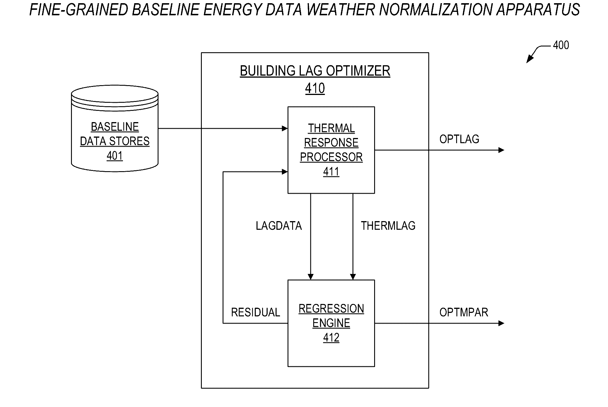
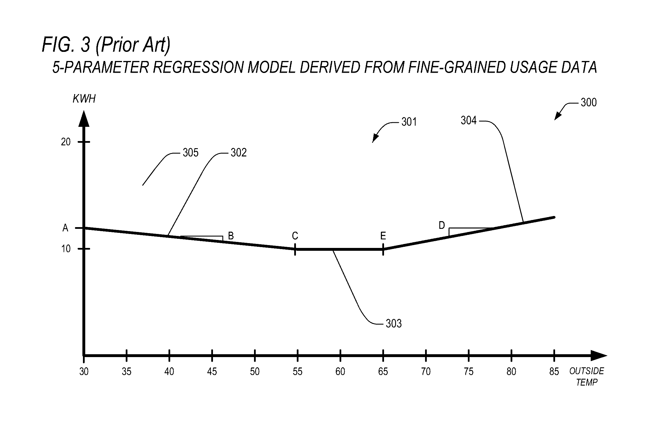
[0019]The present invention, among other applications, is directed to solving the above noted problems and addresses other problems, disadvantages, and limitations of the prior art by providing a superior technique for accurately establishing an energy consumption baseline using consumption data having a much finer granularity than that which has heretofore been provided. In one embodiment, a demand response dispatch system is provided. The system includes a baseline data stores, a building lag optimizer, and a dispatch processor. The baseline data stores is configured to store a plurality of baseline energy use data sets for buildings participating in a demand response program. The building lag optimizer is configured to receive identifiers for the buildings, and is configured to retrieve the plurality of baseline energy use data sets from the baseline data stores for the buildings, and is configured to generate energy use data sets for each of the buildings, each of the energy use data sets having energy consumption values along with corresponding time

Problems solved by technology

One problem with resources such as electricity, water, fossil fuels, and their derivatives (e.g., natural gas) is related to supply and demand.
That is, production of a resource often is not in synchronization with demand for the resource.
In addition, the delivery and transport infrastructure for these resources is limited in that it cannot instantaneously match production levels to provide for constantly fluctuating consumption levels.
Another problem with resources such as water and fossil fuels (which are ubiquitously employed to produce electricity) is their limited supply along with the detrimental impacts (e.g., carbon emissions) of their use.
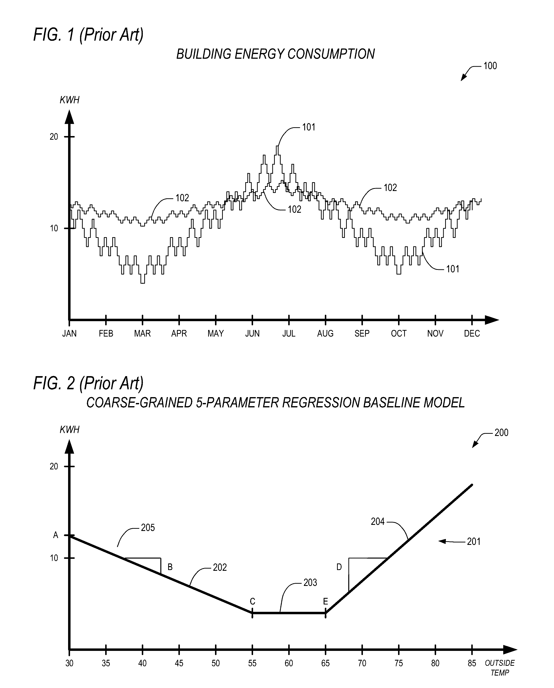
The answers to the above questions are not straightforward, primarily because, as one skilled in the art will appreciate, weather drives cons

Method used


Image

  • Apparatus and method for employing weather induced facility energy consumption characterizations in a demand response dispatch system
  • Apparatus and method for employing weather induced facility energy consumption characterizations in a demand response dispatch system
  • Apparatus and method for employing weather induced facility energy consumption characterizations in a demand response dispatch system

Examples


Embodiment Construction

[0032]Exemplary and illustrative embodiments of the invention are described below. In the interest of clarity, not all features of an actual implementation are described in this specification, for those skilled in the art will appreciate that in the development of any such actual embodiment, numerous implementation specific decisions are made to achieve specific goals, such as compliance with system related and business related constraints, which vary from one implementation to another. Furthermore, it will be appreciated that such a development effort might be complex and time consuming, but would nevertheless be a routine undertaking for those of ordinary skill in the art having the benefit of this disclosure. Various modifications to the preferred embodiment will be apparent to those skilled in the art, and the general principles defined herein may be applied to other embodiments. Therefore, the present invention is not intended to be limited to the particular embodiments shown a...


PUM


Abstract

A method for dispatching buildings in a demand response program event including retrieving a plurality of baseline energy use data sets for the buildings from a baseline data stores; generating data sets for each of the buildings, each set having energy consumption values along with corresponding time and outside temperature values, where the energy consumption values within each set are shifted by one of a plurality of lag values relative to the corresponding time and outside temperature values, and where each of the plurality of lag values is different from other ones of the plurality of lag values; performing a regression analysis on each set to yield regression model parameters and a residual; determining a least valued residual from all residuals yielded, the least valued residual indicating a corresponding energy lag for the each of the buildings; and using energy lags for all of the buildings to generate a dispatch schedule for the demand response program event according to a prioritization of the energy lags.

Description

CROSS-REFERENCE TO RELATED APPLICATIONS[0001]This application is a continuation of the following co-pending U.S. patent application, which is herein incorporated by reference for all intents and purposes.SER.FILINGNO.DATETITLE14 / 674,021Mar. 31, 2015DEMAND RESPONSE DISPATCH SYSTEM(ENER.0132)EMPLOYING WEATHER INDUCED FACILITY ENERGYCONSUMPTION CHARACTERIZATIONS[0002]This application is related to the following co-pending U.S. patent applications, each of which has a common assignee and common inventors.SER.FILINGNO.DATETITLE14 / 673,995Mar. 31, 2015APPARATUS AND METHOD FOR FINE-GRAINED(ENER.0127)WEATHER NORMALIZATION OF ENERGYCONSUMPTION BASELINE DATA14 / 674,004Mar. 31, 2015SYSTEM FOR WEATHER INDUCED FACILITY ENERGY(ENER.0131)CONSUMPTION CHARACTERIZATION       —WEATHER INDUCED FACILITY ENERGY(ENER.0131-C1)CONSUMPTION CHARACTERIZATION MECHANISM14 / 674,033Mar. 31, 2015DEMAND RESPONSE DISPATCH PREDICTION(ENER.0133)SYSTEM       —APPARATUS AND METHOD FOR PREDICTION OF A(ENER.0133-C1)DEMAND RES...

Claims


Application Information

Patent Timeline
IPC IPC(8): H02J3/00G05B13/02
CPCH02J3/00H02J2003/003G05B13/026G06Q50/06G05B2219/2642G06Q10/04G05F1/66G05B15/02H02J3/003H02J2310/12Y02P80/10Y04S20/222Y02B70/3225H04L12/2816Y02B70/30Y04S20/20
Inventor AL-MOHSSEN, HUSAINPARADIS, RICHARD R.BASSA, ANGELA S.
Owner ENEL X NORTH AMERICA INC
Why Eureka
Try Eureka