Communication Device, System and Method

a communication device and low-delay technology, applied in the field of communication devices, systems and methods, can solve the problems of increasing the delay in fec calculation, inability to avoid data packet loss, and inability to reproduce high-quality stream data, so as to achieve the effect of suppressing packet loss

Active Publication Date: 2016-10-06
HITACHI LTD
View PDF19 Cites 13 Cited by
  • Summary
  • Abstract
  • Description
  • Claims
  • Application Information

AI Technical Summary

Benefits of technology

[0015]According to an embodiment of the present invention, packet losses can effectively be suppressed by setting an encoded block size or an encoding processing time and encoded block size of error correction codes.

Problems solved by technology

However, it is not possible to avoid a loss of a data packet caused in passing through a network only with the RTP.
Particularly in an environment where a communication quality of a line is relatively poor, there is a problem that high-quality stream data may not be reproduced.
However, when the number of packets to be input is small, a larger number of original data packets included in the FEC encoded block leads to an increase in delay in FEC calculation.

Method used


Image

  • Communication Device, System and Method
  • Communication Device, System and Method
  • Communication Device, System and Method

Examples


first embodiment

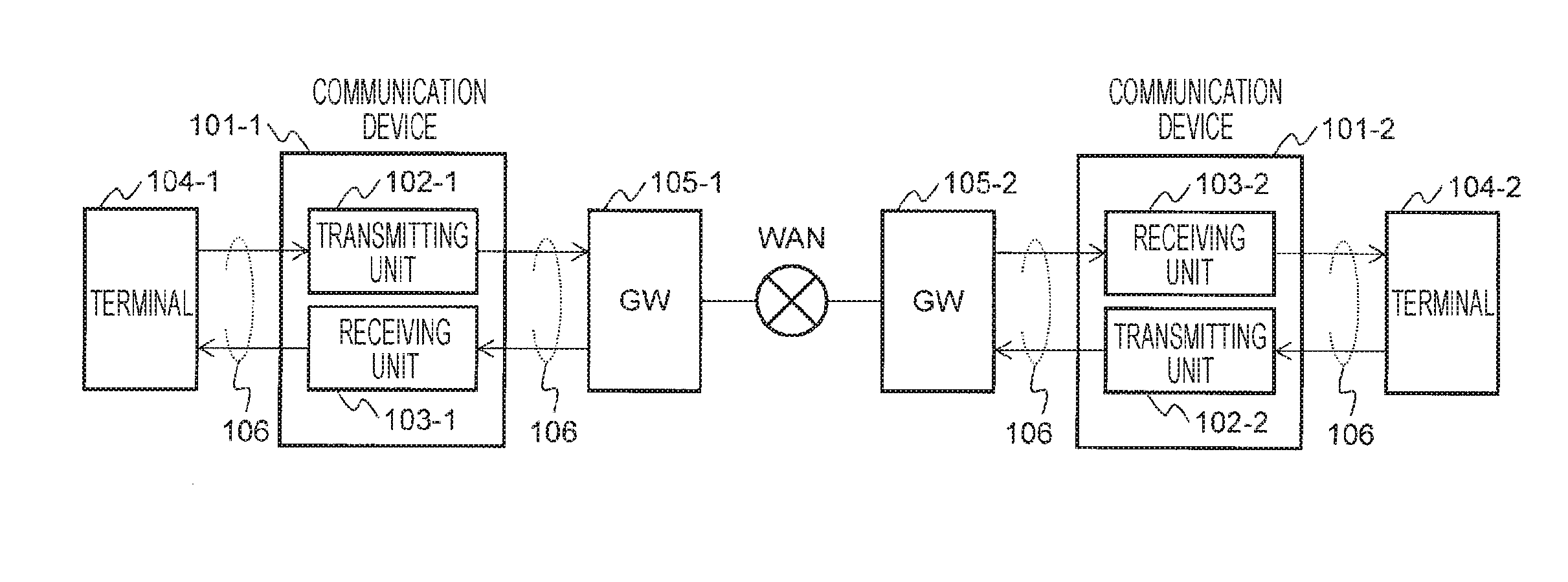
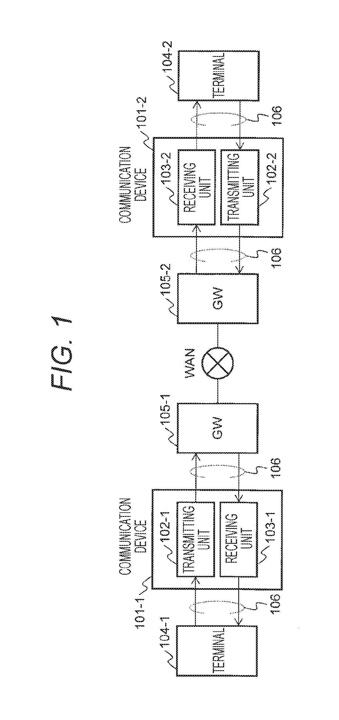
[0027]FIG. 1 is diagram illustrating a configuration of a communication system according to a first embodiment of the present invention. A communication network via a WAN often sees a burst loss that several packets are continuously lost. A communication device according to the present embodiment is a good example to effectively suppress defects of packets due to the burst loss.

[0028](Overall Configuration)

[0029]The embodiment illustrated in FIG. 1 denotes a configuration when terminals 104-1 and 104-2 perform an interactive communication. Communication devices 101 are connected between the terminals 104 and gateways (GWs) 105, and the devices are each connected via a communication line 106 such as Ethernet (registered trademark). The communication line 106 may be wired or wireless. Each communication device 101 includes a transmitting unit 102 and a receiving unit 103. For example, the communication device 101 may be a personal computer (PC). Each terminal 104 may be a device such ...

second embodiment

[0069]In the FEC encoding section 204 of the transmitting unit 102 indicated in the first embodiment, it is assumed that the feedback data including the line quality information such as the burst loss time TBL and an average loss rate have been acquired from the feedback data acquiring section 214. In a case where the average loss rate is higher than a predetermined threshold despite the encoding time T set at a value more than twice the burst loss time TBL, it is thought, for example, that the loss rate is increasing due to a random error rather than a burst error. In this case, the FEC encoding section 204 may improve the loss rate by arbitrarily decrease a value of D derived by calculation. For example, in a case where the average loss rate is higher than the threshold, the FEC encoding section 204 may decrease the value of D calculated by Formula 1 only by 1 and then calculate L by Formula 2. The FEC encoding section 204 determines the loss rate and the threshold again after a c...

third embodiment

[0070]FIG. 7 is a diagram illustrating a configuration of the communication system according to the second embodiment of the present invention. According to the present embodiment, a transmitting unit 102 and a receiving unit 103 can operate independently. It is not always necessary that the transmitting unit 102 and the receiving unit 103 exist in the same device. Therefore, a transmitter can mount only the transmitting unit 102, and a receiver can mount only the receiving unit 103, which makes it possible to subject a one-way communication to FEC encoding processing. In a user setting section 701 of the transmitting unit 102, values such as an encoding time T and a burst loss time TBL are set in advance, and a packet number measuring section 203 and an FEC encoding section 204 execute the FEC encoding processing based on this information of T and TBL. Parameters such as T and TBL described in the user setting section 701 can be changed arbitrarily by a user.


PUM


Abstract

Provided is a method for effectively suppressing packet losses by burst losses without an increase in delay by adaptively or fixedly changing a size of an FEC encoded block even when the number of packets per unit time is small. Each communication device 101 includes a transmitting unit 102 and a receiving unit 103. The transmitting unit 102 has a function of calculating forward error correction (FEC) codes based on the number of packets per encoding time and a value of a burst loss time of a network line. The receiving unit 103 decodes an FEC encoded packet and measures line quality information of the network for transmission to the transmitting unit 102. The transmitting unit 102 transmits the packets at equal intervals for as long as it is required for encoding, and can change a system for calculating FEC based on the burst loss time and the encoding time.

Description

TECHNICAL FIELD[0001]The present invention relates to a communication device, system, and method, and particularly a communication device, system, and method for low-delay communication, applicable for various systems such as a remote monitoring system of a system for remote operation, a remote control system, and a remote monitoring control system.BACKGROUND ART[0002]Recently, there has been increasing demand for a remote monitoring control system that controls on-site devices as well as obtains videos and voice information in remote areas for plant production management and works under severe environments difficult for people to enter. In this case, it is possible to use, for example, a wide area network (WAN) such as the Internet that has been developed as a communication infrastructure for communications with remote areas.[0003]Currently, as a major communication protocol that communicates via the WAN, a transmission control protocol (TCP) and a user datagram protocol (UDP) are ...

Claims


Application Information

Patent Timeline
Patent Type & Authority Applications(United States)
IPC IPC(8): H04L1/00H04L29/06
CPCH04L1/0041H04L1/007H04L1/0073H04L69/22H04L1/0009H04L1/0026H04L1/0075H04L1/0079
Inventor TAKEUCHI, TAKASHIFUJIWARA, RYOSUKE
Owner HITACHI LTD
Why Eureka
Try Eureka