
Transmission rate control method and communication device

a transmission rate control and communication device technology, applied in data switching networks, frequency-division multiplexes, broadcast service distribution, etc., can solve the problem of easy loss of packets, and achieve the effect of suppressing delivery delay and packet loss

Inactive Publication Date: 2011-02-03
SONY CORP
View PDF5 Cites 14 Cited by
  • Summary
  • Abstract
  • Description
  • Claims
  • Application Information

AI Technical Summary

Benefits of technology

[0009]However, in the VTP, the followability to a rapid rate reduction is low, and therefore there is an issue that the packet loss easily occurs. Thus, there has been desired a rate control method that based on the VTP with a small rate variation, a delivery delay and the packet loss can be suppressed even in networks including a wireless environment.
[0010]Thus, the present invention provides a transmission rate control method and a communication device, which can suppress the delivery delay and the packet loss in the streaming delivery on networks including a wireless environment.
[0012]According to the transmission rate control method, the transmission rate is set based on the reception achievement rate that is calculated as the long-term EWMA or short-term EWMA of the reception rate in accordance with network conditions. According to this configuration, in the streaming delivery on networks including a wireless environment, the followability of the transmission rate with respect to the network conditions is enhanced, and the delivery delay and the packet loss can be suppressed.
[0032]As described above, the present invention can provide a transmission rate control method and a communication device, which can suppress the delivery delay and the packet loss in the streaming delivery on networks including a wireless environment.

Problems solved by technology

However, in the VTP, the followability to a rapid rate reduction is low, and therefore there is an issue that the packet loss easily occurs.

Method used


Image

  • Transmission rate control method and communication device
  • Transmission rate control method and communication device
  • Transmission rate control method and communication device

Examples


Embodiment Construction

[0039]Hereinafter, preferred embodiments of the present invention will be described in detail with reference to the appended drawings. Note that, in this specification and the appended drawings, structural elements that have substantially the same function and structure are denoted with the same reference numerals, and repeated explanation of these structural elements is omitted.

[1. Configuration of Communication System]

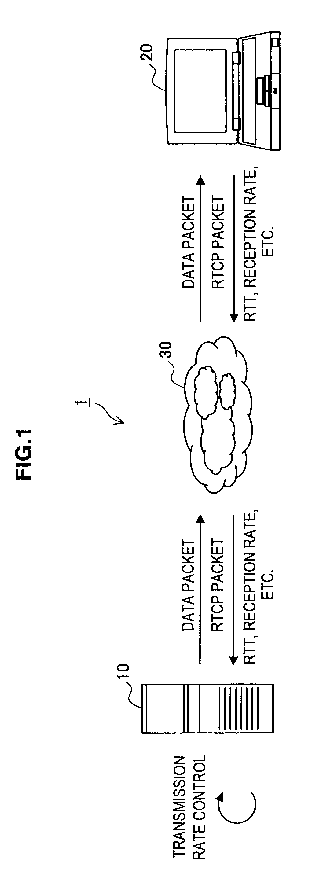
[0040]FIG. 1 is a view showing a configuration of a communication system 1 according to an embodiment of the present invention. The communication system 1 includes a transmission device 10 and a reception device 20 transmitting and receiving data packets through a packet-switched network 30 including a wireless environment. The network 30 is, for example, an interne, an intranet, an extranet, and a satellite connection and includes in at least a part a wireless environment. The transmission device 10 and the reception device 20 are information processors such as a se...


PUM


Abstract

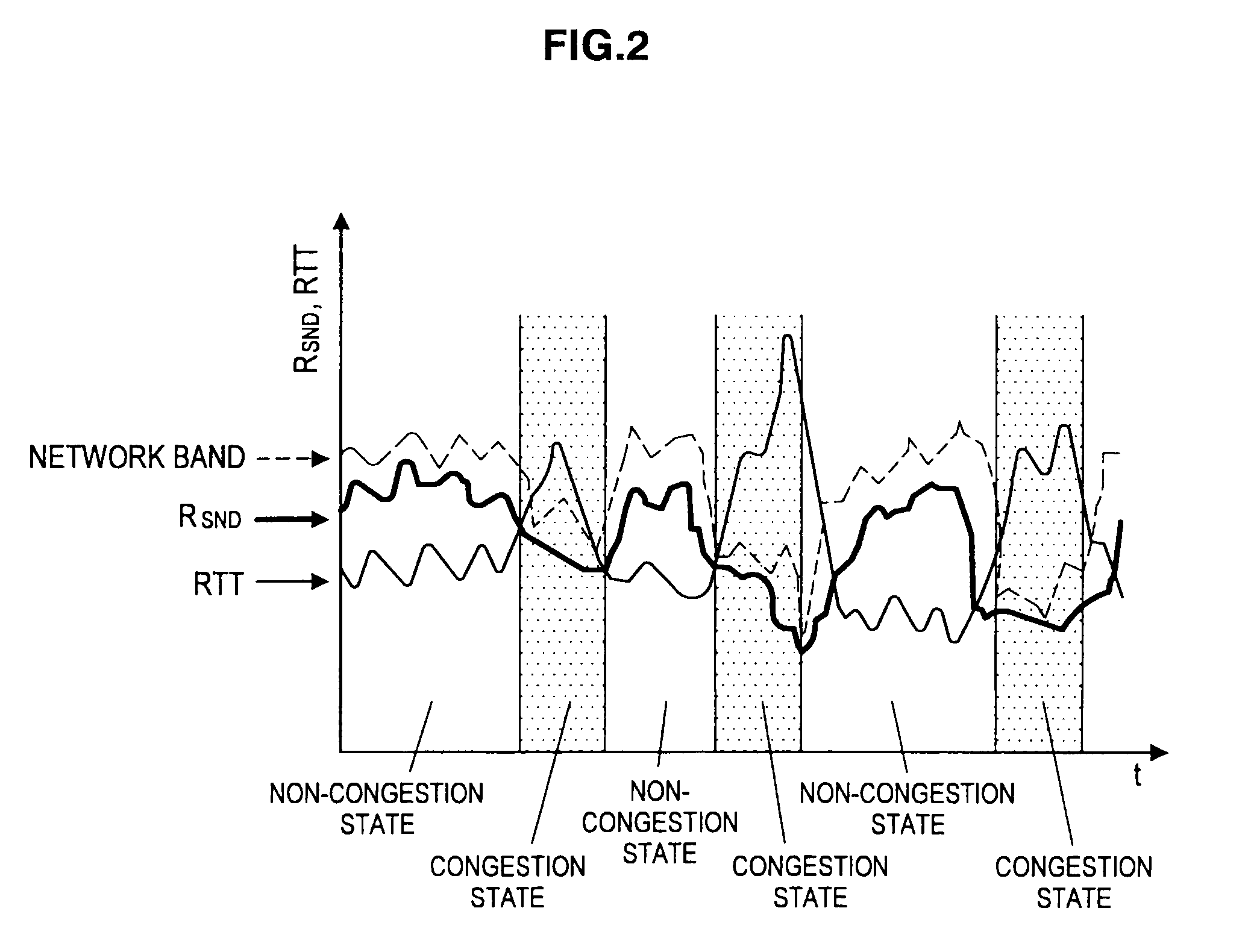
There is provided a transmission rate control method. In this method, data is transmitted to a receiver at the most recent transmission rate RSNDt-1, and an RTCP packet including a reception rate RRCVt of the data is received from the receiver. When a network is in a congestion state, or when the network is in a non-congestion state and the most recent reception achievement rate RARt-1 is higher than the reception rate RRCVt, a reception achievement rate RARt is calculated as a long-term EWMA of the reception rate RRCV. When the network is in the non-congestion state and the most recent reception achievement rate RARt-1 is lower than the reception rate RRCVt, or when a time-out of the RTCP packet occurs, the reception achievement rate RARt is calculated as a short-term EWMA of the reception rate RRCV. A transmission rate RSNDt is set based on the reception achievement rate RARt.

Description

BACKGROUND OF THE INVENTION[0001]1. Field of the Invention[0002]The present invention relates to a transmission rate control method and a communication device.[0003]2. Description of the Related Art[0004]In a packet-switched streaming delivery system, video data and audio data are downloaded from a server side to a client side to be buffered, and thereafter to be reproduced, whereby almost real-time streaming delivery is realized. However, in a system such as a video conferencing system emphasizing real-time performance, in order to avoid reproduction delay due to buffering, a transmission rate is regulated on the server side in accordance with network conditions to prevent a packet loss.[0005]When end-to-end communication is performed on a packet-switched network, TCP (Transport Control Protocol) is utilized for the purpose of controlling a delivery rate in a transport layer. However, in the TCP, a variation of the delivery rate is large, and automatic retransmission is performed s...

Claims


Application Information

Patent Timeline
IPC IPC(8): H04L12/26H04L12/801H04L12/825H04L12/911H04L12/931H04L29/08H04W4/06H04W28/02H04W28/22
CPCH04L43/0894H04L47/10H04L65/80H04L47/25H04L65/608H04L47/14H04W28/10H04L65/65H04W8/04
Inventor WAKUDA, KENSAKUOIKAWA, TOMOYA
Owner SONY CORP
Learn More