Radio terminal and communication terminal
a technology of communication terminal and radio terminal, which is applied in the field of radio terminal and communication terminal, can solve the problems of difficult to appropriately control the amount of packets stored in the buffer, packet loss, etc., and achieve the effect of suppressing packet loss and suppressing abrupt changes in packet reproduction ra
- Summary
- Abstract
- Description
- Claims
- Application Information
AI Technical Summary
Benefits of technology
Problems solved by technology
Method used
Image
Examples
first embodiment
[First Embodiment]
(Configuration of Communication System)
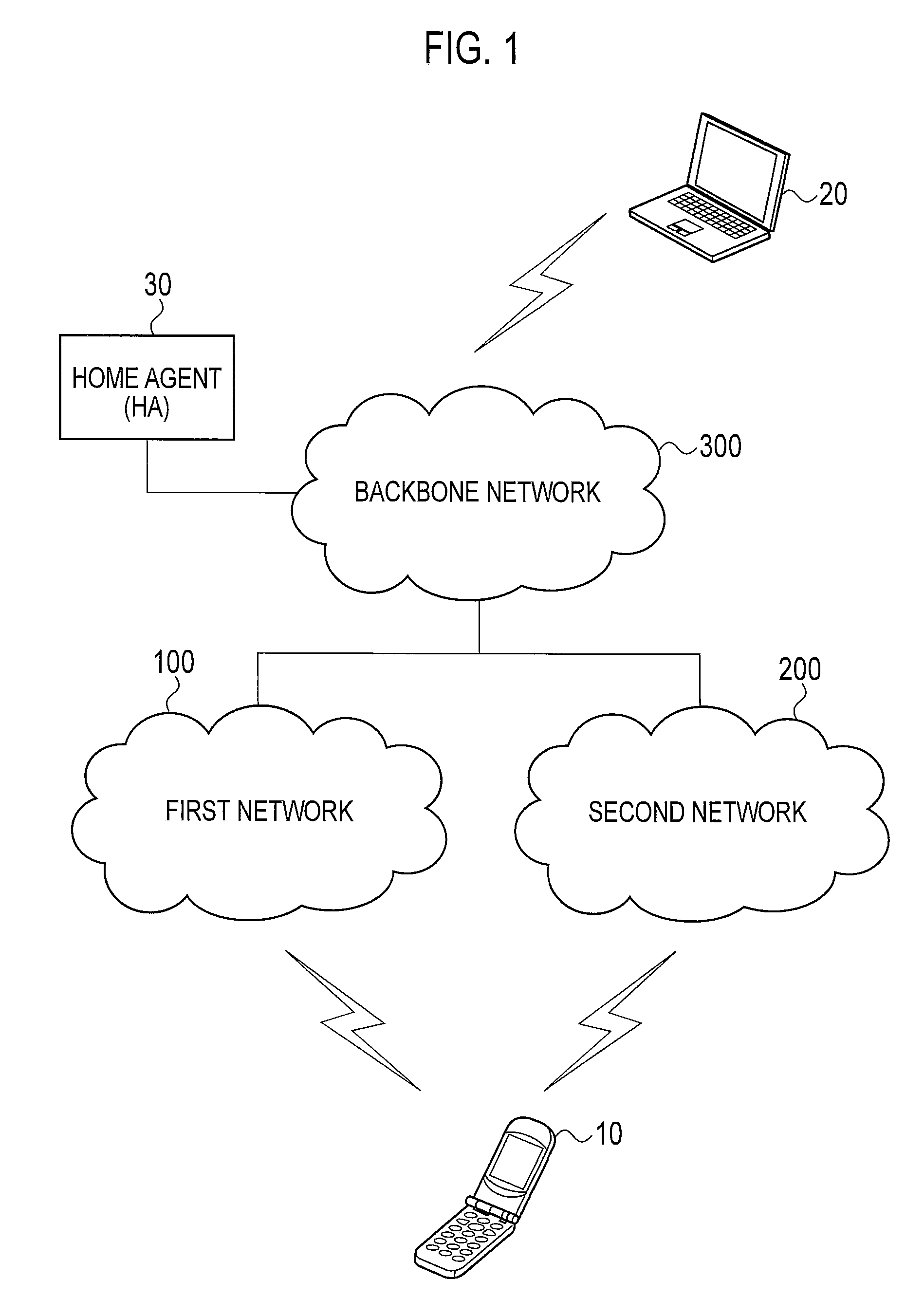
[0042]Hereinbelow, a configuration of a communication system according to a first embodiment will be described with reference to the drawings. FIG. 1 is a diagram showing the configuration of the communication system according to the first embodiment.
[0043]As shown in FIG. 1, the communication system includes a radio terminal 10, a communication terminal 20, a home agent 30, a first network 100, a second network 200 and a backbone network 300.
[0044]In the first embodiment, a delay time of the first network 100 is shorter than a delay time of the second network 200. The radio terminal 10 communicates with the communication terminal 20 through the first network 100 or the second network 200.
[0045]Note that a delay time of a network is a concept which includes not only a time that a packet from the communication terminal 20 (correspondent terminal) held in the network (holding time) but also variation (jitter) in the holding time...
second embodiment
[Second Embodiment]
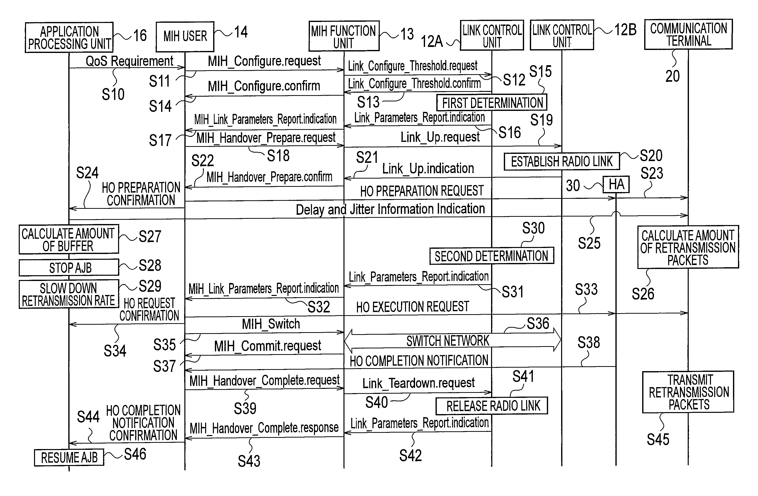
[0188]Hereinbelow, a second embodiment will be described with reference to the drawings. The following description will be given mainly of differences between the first embodiment and the second embodiment.
[0189]The first embodiment has been described mainly by referring to a flow of packets from the communication terminal 20 to the radio terminal 10. In contrast, the second embodiment will be described by referring mainly to a flow of packets from the radio terminal 10 to the communication terminal 20.
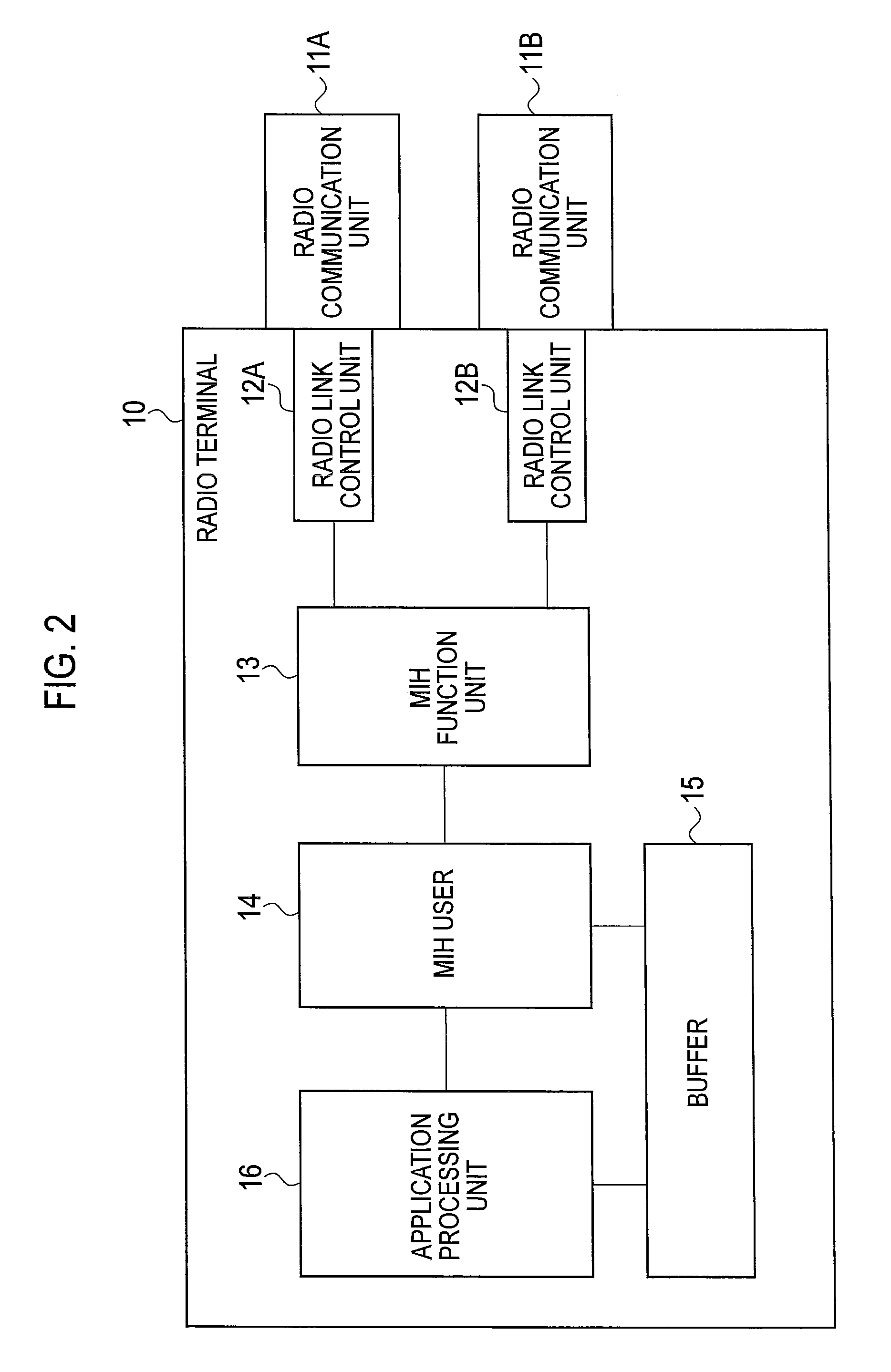
[0190]That is, the second embodiment is different from the first embodiment in that the functions of the application processing unit 16 of the radio terminal 10 is switched with the functions of the application processing unit 26 of the communication terminal 20. To be more specific, the application processing unit 26 of the communication terminal 20 has the functions of the application processing unit 16 of the first embodiment. The application processing unit 16 o...
example 1
(Example 1 of Packet Reproduction Rate Control)
[0194]Hereinafter, an example 1 of a packet reproduction rate control according to the second embodiment will be described with reference to the drawings. FIG. 8 is a diagram showing the example 1 of a packet reproduction rate control according to the second embodiment. Here, a case where the radio terminal 10 corresponds to a SCoA (single care of address) is exemplified. With the SCoA, the radio terminal 10 transmits packets through one of the first network 100 and the second network 200.
[0195]At time t1, the communication terminal 20 receives a handover preparation request from the home agent 30. At time t1, the communication terminal 20 changes the packet reproduction rate to a lower (slower) rate than the predetermined rate. In addition, at time t1, the communication terminal 20 stops the AJB control.
[0196]At time t2, the communication terminal 20 receives a handover execution request from the home agent 30. It should be noted that ...
PUM
 Abstract
Description
Claims
Application Information
 - R&D
- Intellectual Property
- Life Sciences
- Materials
- Tech Scout
- Unparalleled Data Quality
- Higher Quality Content
- 60% Fewer Hallucinations
Browse by: Latest US Patents, China's latest patents, Technical Efficacy Thesaurus, Application Domain, Technology Topic, Popular Technical Reports.
© 2025 PatSnap. All rights reserved.Legal|Privacy policy|Modern Slavery Act Transparency Statement|Sitemap|About US| Contact US: help@patsnap.com


