Radio terminal and communication terminal

a technology of communication terminal and radio terminal, which is applied in the field of radio terminal and communication terminal, can solve the problems of difficult to appropriately control the amount of packets stored in the buffer, packet loss, etc., and achieve the effect of suppressing packet loss and suppressing abrupt changes in packet reproduction ra

Inactive Publication Date: 2011-08-25
KYOCERA CORP
View PDF10 Cites 8 Cited by
  • Summary
  • Abstract
  • Description
  • Claims
  • Application Information

AI Technical Summary

Benefits of technology

[0186]In the first embodiment, the radio terminal 10 changes the packet reproduction rate to a rate slower than the predetermined rate after transmission of a handover preparation request. Accordingly, it is possible to promptly bring the amount of packets stored in the buffer 15 close to the optimal packet amount in the second network 200 (the second optimal packet amount), after handover from the first network 100 to the second network 200. It is also possible to suppress packet losses.
[0187]In the first embodiment, the radio terminal 10 stops the AJB control after transmission of the handover preparation request. Accordingly, it is possible to suppress abrupt changes in the packet reproduction rate due to the AJB control, when handover is performed from the first network 100 to the second network 200.Second Embodiment
[0188]Hereinbelow, a second embodiment will be described with reference to the drawings. The following description will be given mainly of differences between the first embodiment and the second embodiment.
[0189]The first embodiment has been described mainly by referring to a flow of packets from the communication terminal 20 to the radio terminal 10. In contrast, the second embodiment will be described by referring mainly to a flow of packets from the radio terminal 10 to the communication terminal 20.
[0190]That is, the second embodiment is different from the first embodiment in that the functions of the application processing unit 16 of the radio terminal 10 is switched with the functions of the application processing unit 26 of the communication terminal 20. To be more specific, the application processing unit 26 of the communication terminal 20 has the functions of the application processing unit 16 of the first embodiment. The application processing unit 16 of the radio terminal 10 has the functions of the application processing unit 26 of the first embodiment.
[0191]In the second embodiment, in the same manner as the first embodiment, a delay time of the first network 100 is shorter than a delay time of the second network 200. In the second embodiment, in the same manner as the first embodiment, the radio terminal 10 performs handover from the first network 100 to the second network 200.

Problems solved by technology

This may cause a packet loss.
Thus, it is difficult to appropriately control the amount of packets stored in the buffer after handover from the first network to the second network.

Method used


Image

  • Radio terminal and communication terminal
  • Radio terminal and communication terminal
  • Radio terminal and communication terminal

Examples


first embodiment

(Configuration of Communication System)

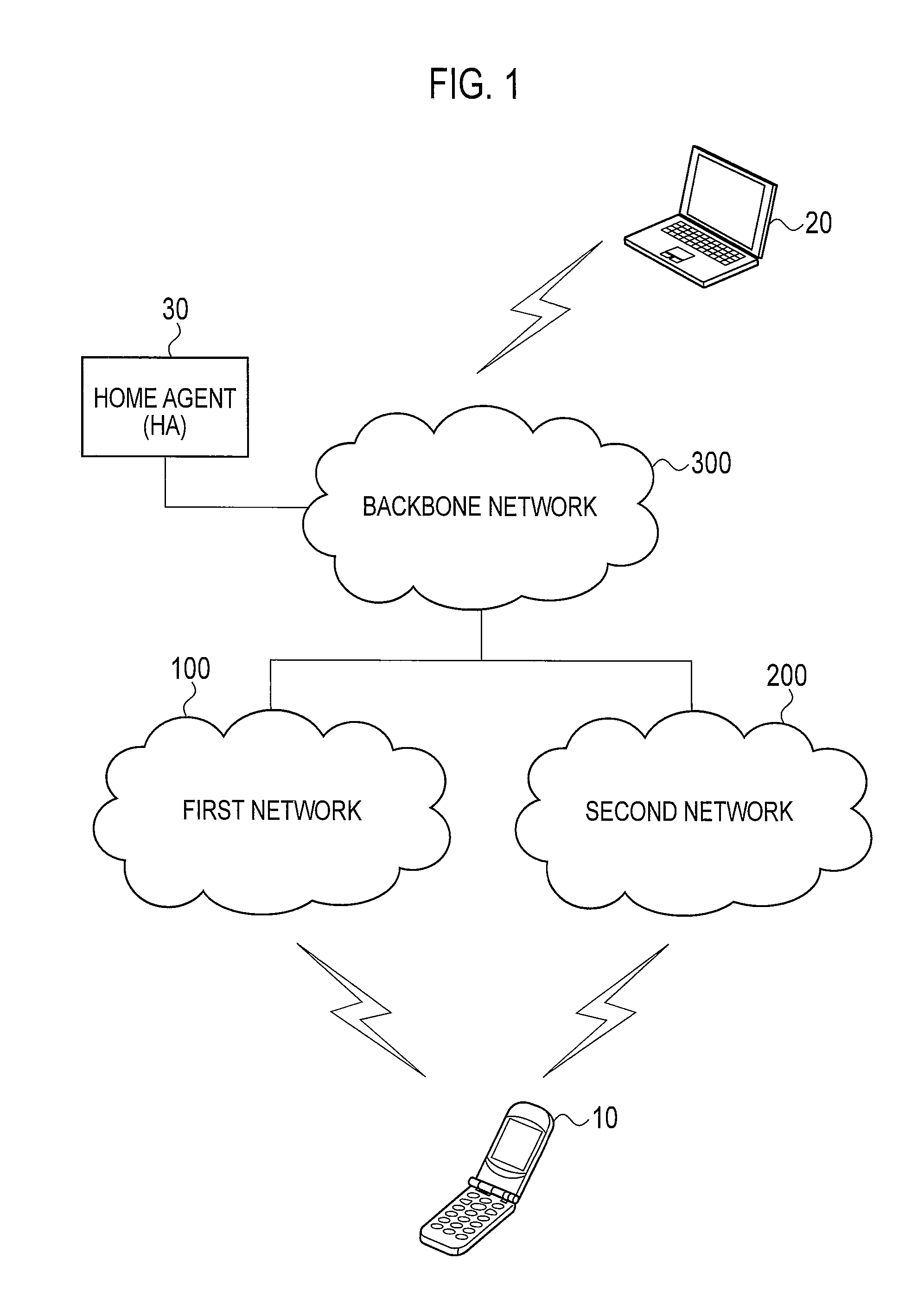
[0042]Hereinbelow, a configuration of a communication system according to a first embodiment will be described with reference to the drawings. FIG. 1 is a diagram showing the configuration of the communication system according to the first embodiment.

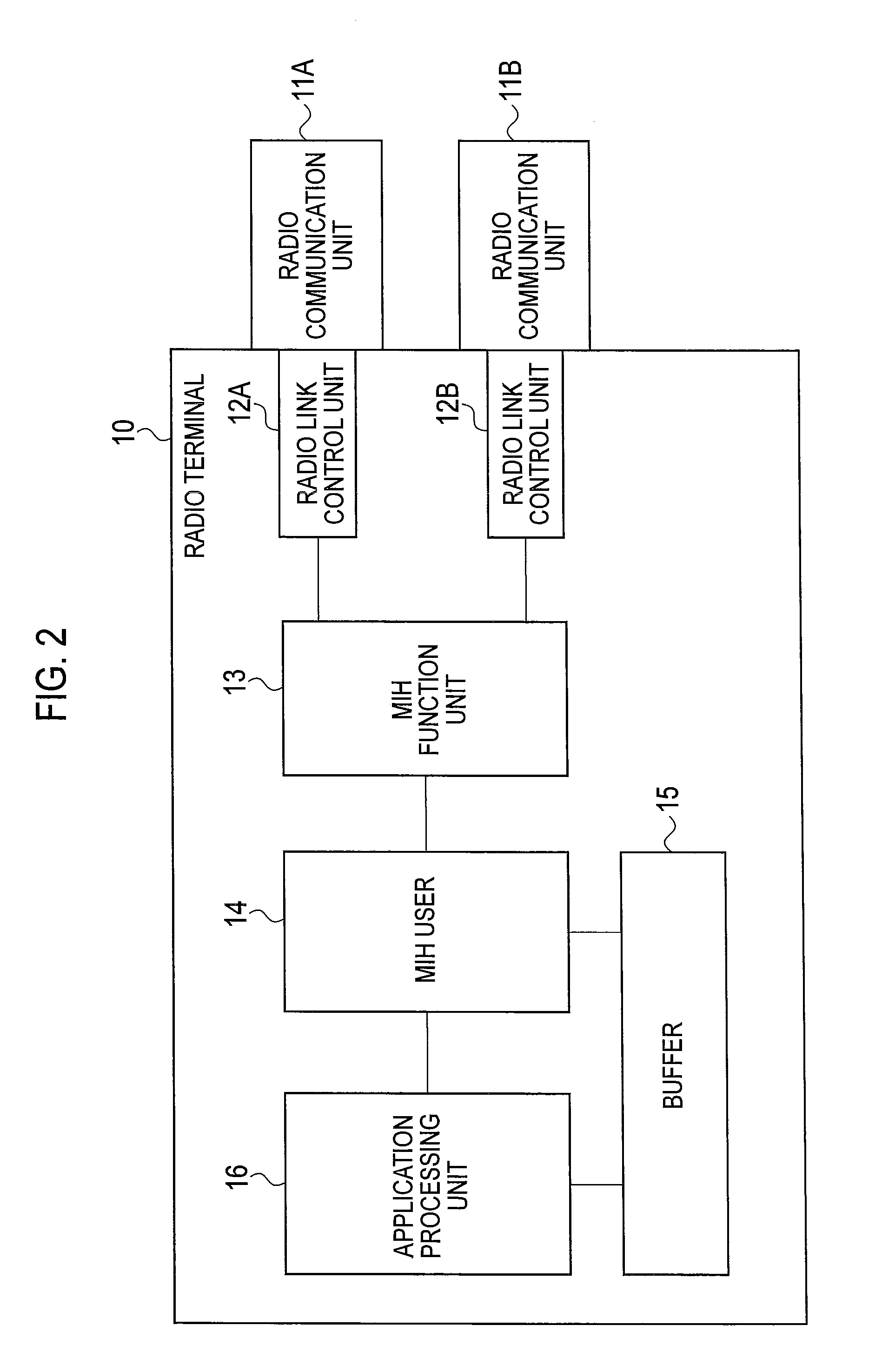
[0043]As shown in FIG. 1, the communication system includes a radio terminal 10, a communication terminal 20, a home agent 30, a first network 100, a second network 200 and a backbone network 300.

[0044]In the first embodiment, a delay time of the first network 100 is shorter than a delay time of the second network 200. The radio terminal 10 communicates with the communication terminal 20 through the first network 100 or the second network 200.

[0045]Note that a delay time of a network is a concept which includes not only a time that a packet from the communication terminal 20 (correspondent terminal) held in the network (holding time) but also variation (jitter) in the holding time. A holding time i...

second embodiment

[0188]Hereinbelow, a second embodiment will be described with reference to the drawings. The following description will be given mainly of differences between the first embodiment and the second embodiment.

[0189]The first embodiment has been described mainly by referring to a flow of packets from the communication terminal 20 to the radio terminal 10. In contrast, the second embodiment will be described by referring mainly to a flow of packets from the radio terminal 10 to the communication terminal 20.

[0190]That is, the second embodiment is different from the first embodiment in that the functions of the application processing unit 16 of the radio terminal 10 is switched with the functions of the application processing unit 26 of the communication terminal 20. To be more specific, the application processing unit 26 of the communication terminal 20 has the functions of the application processing unit 16 of the first embodiment. The application processing unit 16 of the radio termina...

example 1

of Packet Reproduction Rate Control

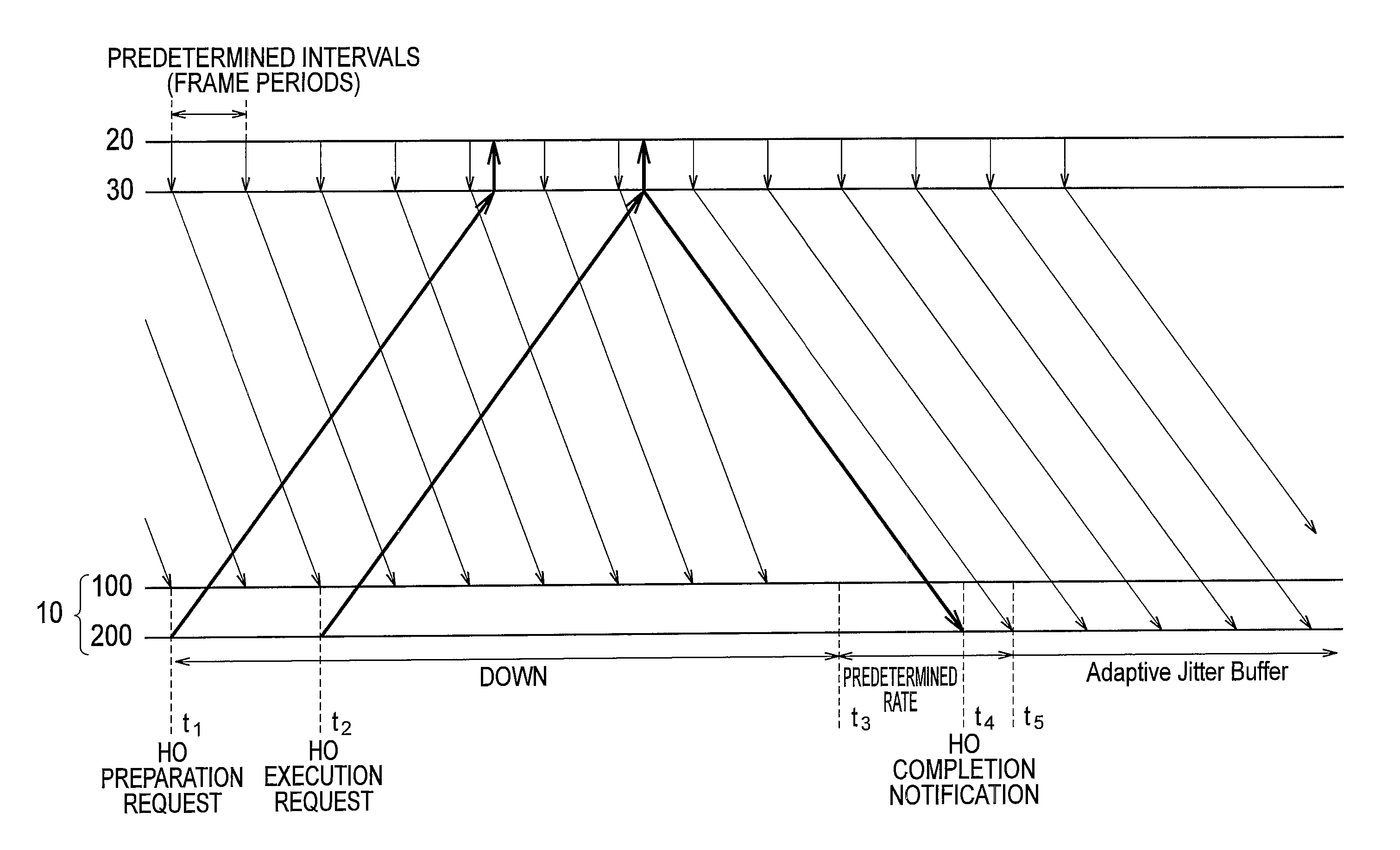
[0194]Hereinafter, an example 1 of a packet reproduction rate control according to the second embodiment will be described with reference to the drawings. FIG. 8 is a diagram showing the example 1 of a packet reproduction rate control according to the second embodiment. Here, a case where the radio terminal 10 corresponds to a SCoA (single care of address) is exemplified. With the SCoA, the radio terminal 10 transmits packets through one of the first network 100 and the second network 200.

[0195]At time t1, the communication terminal 20 receives a handover preparation request from the home agent 30. At time t1, the communication terminal 20 changes the packet reproduction rate to a lower (slower) rate than the predetermined rate. In addition, at time t1, the communication terminal 20 stops the AJB control.

[0196]At time t2, the communication terminal 20 receives a handover execution request from the home agent 30. It should be noted that since the pa...


PUM


Abstract

A radio terminal (10) comprises a radio communication unit (11) that receives packets via a first or second network at predetermined intervals; a buffer (15) that temporarily stores packets received by a receiving unit; a radio communication unit (11) that transmits a preparation request for a handover from the first network to the second network; and an application processing unit (16) that reproduces the packets stored in the buffer (15) at a rate that is established in accordance with the predetermined intervals. The application processing unit (16) changes a packet reproduction rate to a rate slower than the predetermined rate in response to transmission of the preparation request for handover, thereby increases the amount of packets stored in the buffer.

Description

TECHNICAL FIELD[0001]The present invention relates to a radio terminal and a communication terminal which communicate through a first network or a second network having a longer delay time than the first network.BACKGROUND ART[0002]Conventionally, a radio terminal which performs real-time communication (such as VoIP) with a communication terminal (correspondent terminal) through a network is known (see Patent Document 1, for example). The radio terminal is provided with a buffer for temporarily storing packets to absorb a delay time of the network. The amount of packets stored in the buffer is determined according to the delay time of the network. Note that a delay time of a network is a concept which includes not only a time that a packet from the communication terminal (correspondent terminal) held in the network (holding time) but also variation (jitter) in the holding time.[0003]In addition, an AJB (adaptive jitter buffer) control technique targeted for a single network is propo...

Claims


Application Information

Patent Timeline
Patent Type & Authority Applications(United States)
IPC IPC(8): H04W36/02H04W24/00
CPCH04W36/14H04W36/02H04W88/06
Inventor YOKOTA, TOMOYOSHI
Owner KYOCERA CORP
Why Eureka
Try Eureka