
Pneumatic Tire

a technology of pneumatic tires and sound-absorbing components, which is applied in the field of pneumatic tires, can solve the problems of low manufacturing cost, cavernous resonance of pneumatic tires, and easy peeling of sound-absorbing components from tire inner surfaces, and achieve excellent fixing strength of sound-absorbing components. , the effect of easy performan

Active Publication Date: 2016-10-13
YOKOHAMA RUBBER CO LTD
View PDF7 Cites 7 Cited by
  • Summary
  • Abstract
  • Description
  • Claims
  • Application Information

AI Technical Summary

Benefits of technology

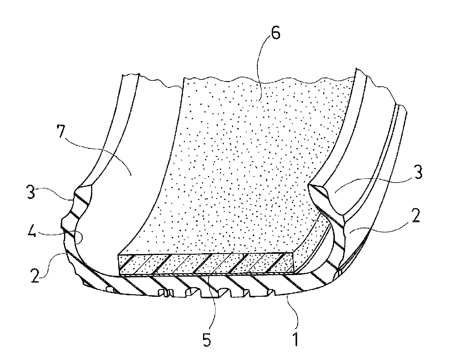
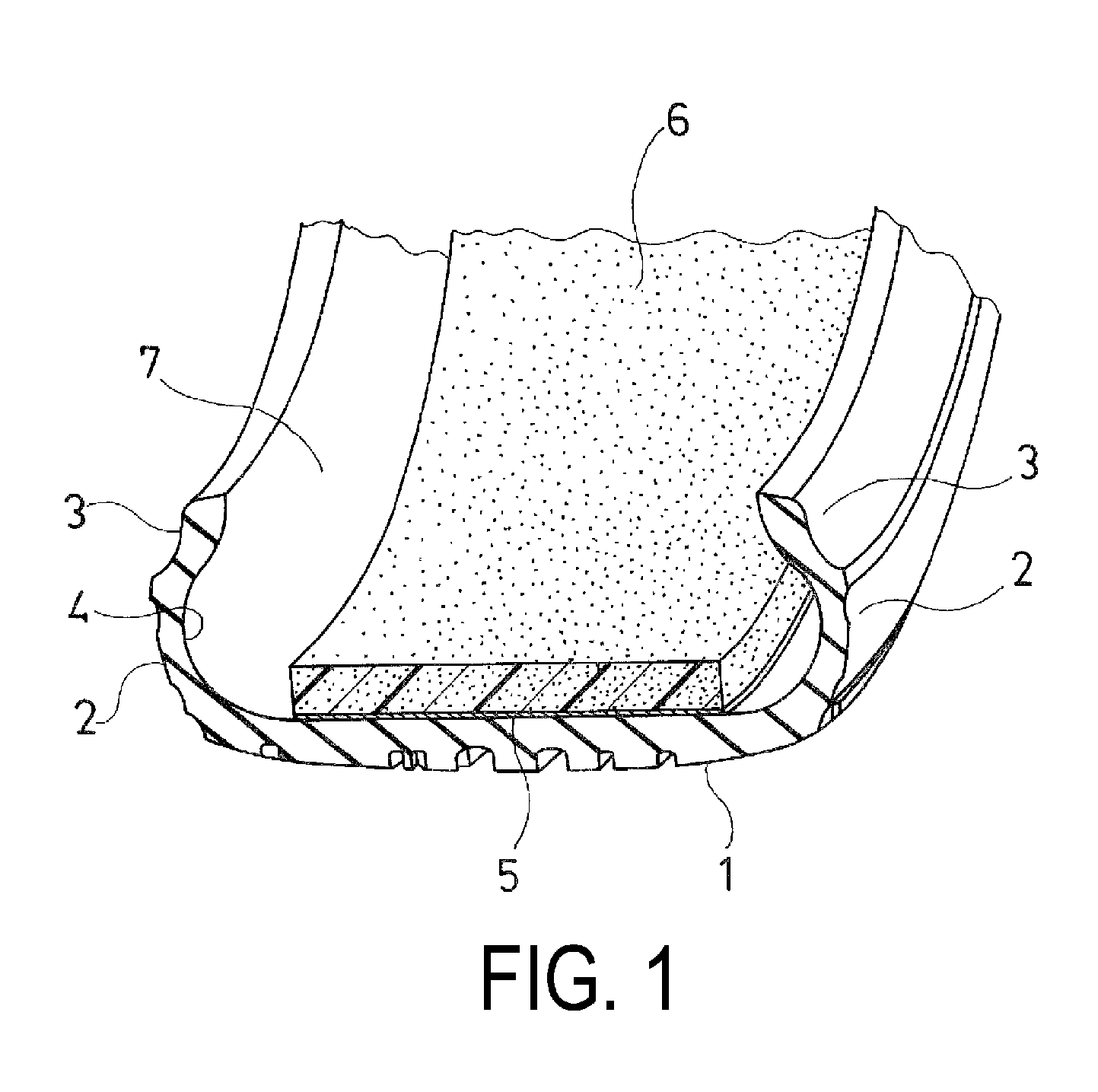
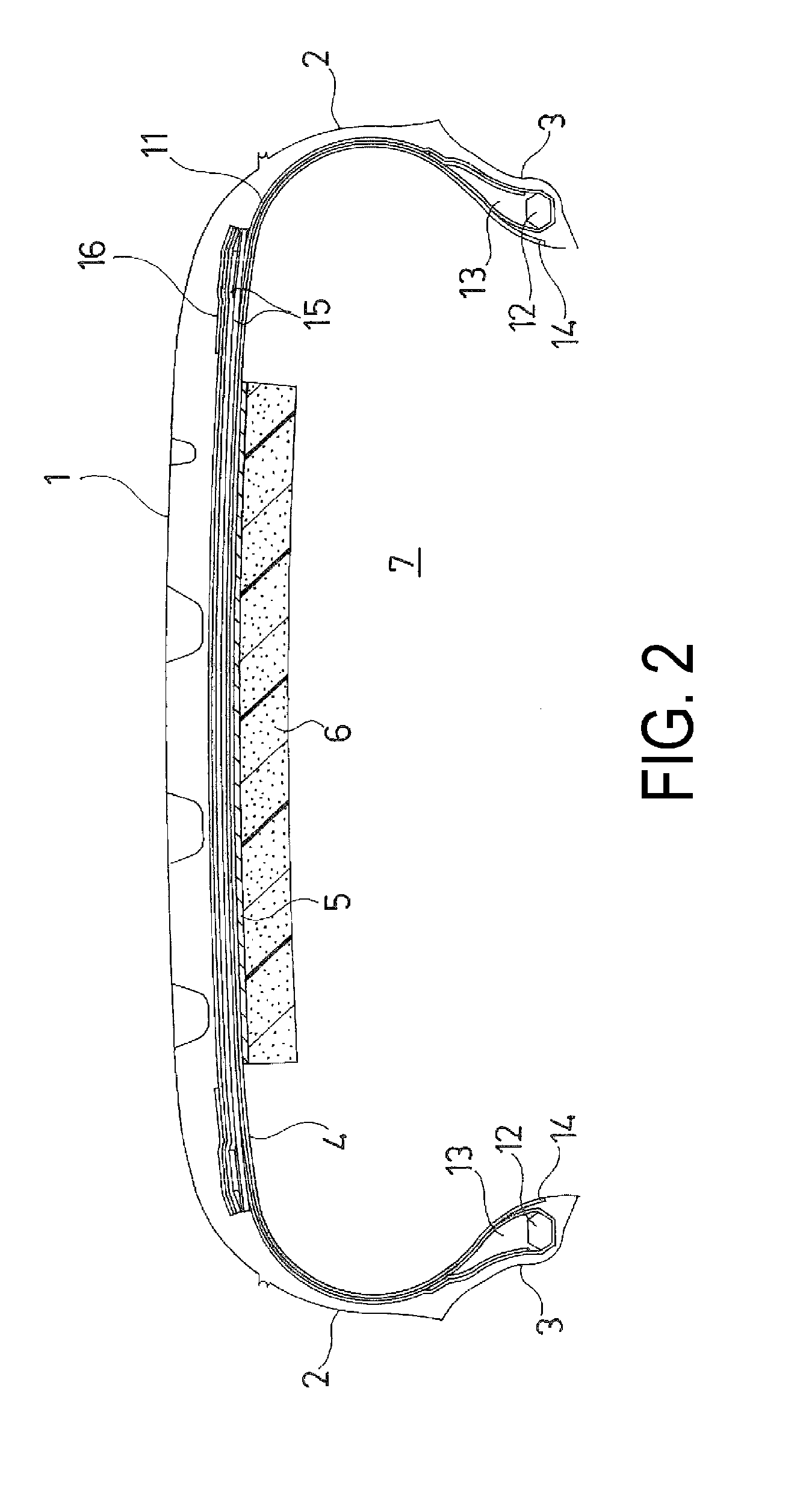
The present technology provides a pneumatic tire that can prevent a reduction in the fixing strength of a sound-absorbing member and peeling of the sound-absorbing member, caused by differences in levels at splice portions of tire constituent members. This is achieved by arranging the sound-absorbing member intermittently along the tire inner surface, at positions corresponding to the splice portions of the tire constituent members. The absence of the sound-absorbing member at the splice portion helps to avoid deterioration in initial adhesiveness and adhesion durability of the sound-absorbing member. The technology also suggests the use of a single sound-absorbing member that has a uniform thickness and cross-sectional shape, which maximizes the content of the sound-absorbing member and reduces manufacturing costs. The ratio of the volume of the sound-absorbing member to the volume of the cavity formed inside the tire during rim assembly should be greater than 20% to achieve an excellent noise reduction effect.

Problems solved by technology

One cause of noise generated in pneumatic tires is cavernous resonance due to vibrations in the air filling the tire interior.
Therefore, in a case where the sound-absorbing member is arranged to cross the splice portion of the tire constituent members, there is a problem in that the sound-absorbing member is easily peeled from the tire inner surface.
In addition, the manufacturing costs are also low because the sound-absorbing member having this shape is easily processed.

Method used


Image

  • Pneumatic Tire
  • Pneumatic Tire
  • Pneumatic Tire

Examples


examples

[0038]Based on pneumatic tires with a tire size of 195 / 65R15 including a tread section forming an annular shape extending in a tire circumferential direction, a pair of side wall sections arranged on both sides of the tread section, and a pair of bead sections arranged inside in a tire radial direction of the side wall sections, in which a belt-shaped sound-absorbing member is adhered to a region corresponding to the tread section in the tire inner surface, along the tire circumferential direction and via an adhesive layer, tires of Comparative Example 1 and Working Examples 1 to 3 were manufactured in which the arrangement state of the sound-absorbing member was different.

[0039]In Comparative Example 1, the belt-shaped sound-absorbing member was arranged over the entire region on the tire circumference without providing a missing section.

[0040]In Working Example 1, the sound-absorbing member was arranged intermittently in the tire circumferential direction as in FIG. 3, the section...


PUM


Abstract

Provided is a pneumatic tire comprising a tread section, a side wall section, and a bead section. A tire constituent member is provided in at least the tread section, extending along the tire circumferential direction and spliced at any positions in the tire circumferential direction. A belt-shaped sound-absorbing member is adhered to a region corresponding to the tread section in the tire inner surface, along the tire circumferential direction and via an adhesive layer. The sound-absorbing member is arranged intermittently along the tire circumferential direction. Sections where the sound-absorbing member is missing are arranged at positions corresponding to the splice portions of the tire constituent member and the sound-absorbing member is arranged so as to not overlap the splice portions.

Description

TECHNICAL FIELD[0001]The present technology relates to a pneumatic tire in which a belt-shaped sound-absorbing member is adhered to a region corresponding to a tread section on a tire inner surface; and particularly relates to a pneumatic tire capable of avoiding reduction in the fixing strength of a sound-absorbing member that is caused by differences in levels at a splice portion of tire constituent members and suppressing peeling of the sound-absorbing member.BACKGROUND ART[0002]One cause of noise generated in pneumatic tires is cavernous resonance due to vibrations in the air filling the tire interior. This cavity resonance is generated by the tread section vibrating due to unevenness of the road surface and the vibrations of the tread section vibrating the air in the interior of the tire when the tire is rolling.[0003]Disposing a sound-absorbing member inside the cavity formed between the tire and the wheel rim has been proposed as a method for reducing noise caused by this cav...

Claims


Application Information

Patent Timeline
IPC IPC(8): B60C19/00
CPCB60C19/002B29D30/0061
Inventor TANNO, ATSUSHI
Owner YOKOHAMA RUBBER CO LTD
Learn More