System and method for magnetically launching projectiles or spacecraft

a magnetic and rocket technology, applied in the field of system and method for electromagnetically rocketing payloads, can solve the problems of limited maximum practical velocity of coil guns, limited maximum practical velocity of launched projectiles, and need to replace rails on a regular basis, so as to reduce the cost of power conditioning, eliminate mechanical contact and friction of payloads, and reduce the effect of friction

Inactive Publication Date: 2016-10-13
POWELL JAMES R
View PDF0 Cites 9 Cited by
  • Summary
  • Abstract
  • Description
  • Claims
  • Application Information

AI Technical Summary

Benefits of technology

[0013]Briefly, and in general terms, the present invention provides for an electromagnetic launcher, an electromagnetic launch system and a method for electromagnetically launching a launch craft for carrying payloads such as projectiles, launch vehicles, spacecraft, aircraft, missiles, rockets, or the like, that utilizes magnetic levitation, stabilization and propulsion, and that employs a transverse direct current magnetic field generated in superconducting cables extending along a launch tube to eliminate mechanical contact and friction of the payload with a launch tube wall. Upper and lower conducting metal plates and loops of conducting material are also provided on the launch craft for magnetic levitation, stabilization and propulsion of the launch craft in cooperation with the transverse direct current magnetic field provided by the electromagnetic launcher to be simpler and less costly, allowing power conditioning to be simplified and less costly, and the electromagnetic launcher includes a launch tube with electrically conducting rails energized along the length of the rails, allowing elimination of expensive, complex electronic switching.

Problems solved by technology

However, such railgun systems typically have a maximum practical launch velocity achievable with railguns and is on the order of 3 kilometers per second, which constrains the range of projectiles launched on earth to only a few hundred miles, and is far below the velocity needed to achieve orbit for a payloads, which is on the order of 8 kilometers per second.
Furthermore, because railguns commonly require that an armature physically contact the rails, the rails must be replaced on a regular basis due to the extreme mechanical stresses and erosion present with this technology.
While projectiles launched by such coil guns need not contact any rails on the inside of the launch tube, as is the case with railguns, such coil guns also have a limited maximum practical velocity, due to the need to sequentially and precisely switch large currents through the series of coils on short (sub-microsecond) time scales.
This constraint limits the maximum practical velocities and masses of the launched projectiles.
While such magnetic levitation or maglev launch systems based on the magnetic acceleration of spacecraft equipped with superconducting loops can achieve orbital speeds of 8 kilometers per second or greater with potentially much lower launch costs than rockets, such conventional maglev launch systems are difficult to scale down to smaller systems such as those optimized for launching small satellites on the order of 100 kilograms, and typically requires specialized power conditioning equipment to generate the necessary AC current required to accelerate the vehicle.
While such magnetic levitation systems can potentially be used for launch systems with launch tubes less than 50 km long providing moderate accelerations of less than 500 m s2 (50 g), such magnetic levitation systems are typically prohibitively expensive for shorter launch systems necessarily requiring higher accelerations, and typically require that spacecraft launched in this manner to have sufficient superconductor cables to carry large currents (500,000 to 1,000,000 amps), which can be prohibitively costly for the launch of small payloads on the order of 100 kg.
Furthermore, such maglev launch systems that use high current superconducting loops on the payload being launched typically require a complex travelling AC current wave in the rails on the walls of the launch tube that pushes on the superconducting magnets on the payload to accelerate the payload.

Method used


Image

  • System and method for magnetically launching projectiles or spacecraft
  • System and method for magnetically launching projectiles or spacecraft
  • System and method for magnetically launching projectiles or spacecraft

Examples


first embodiment

Operation

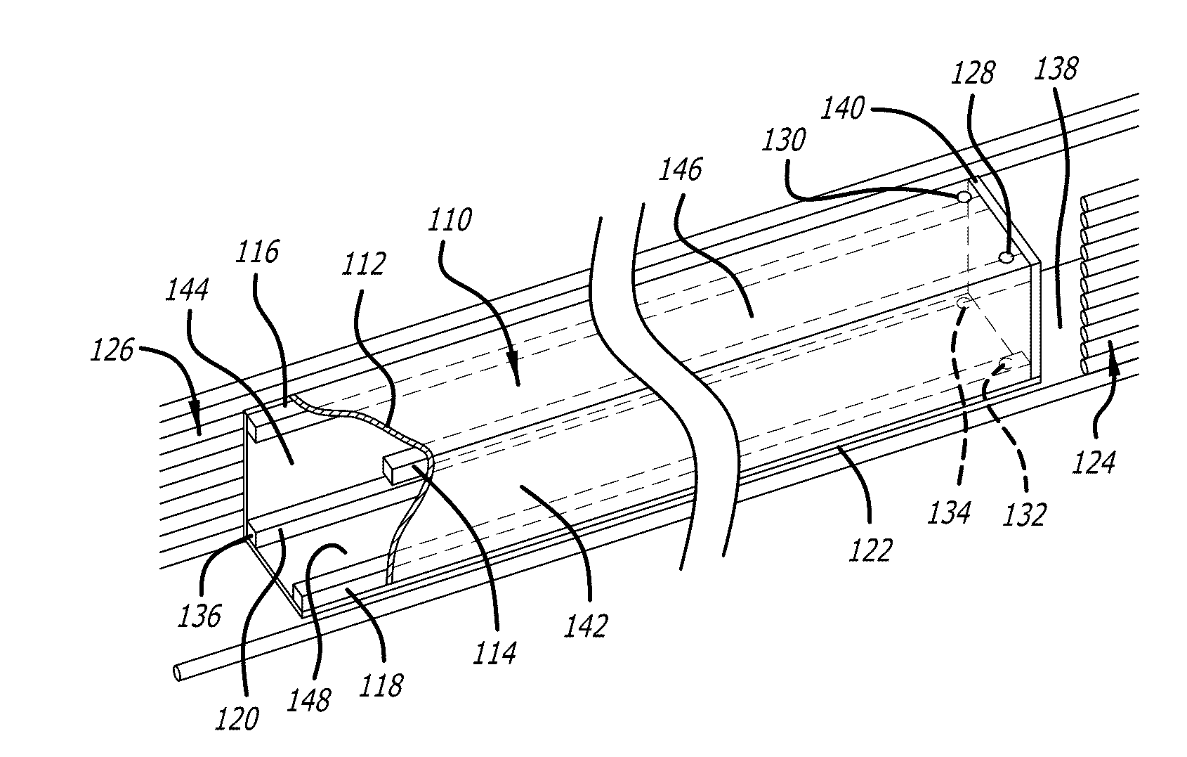
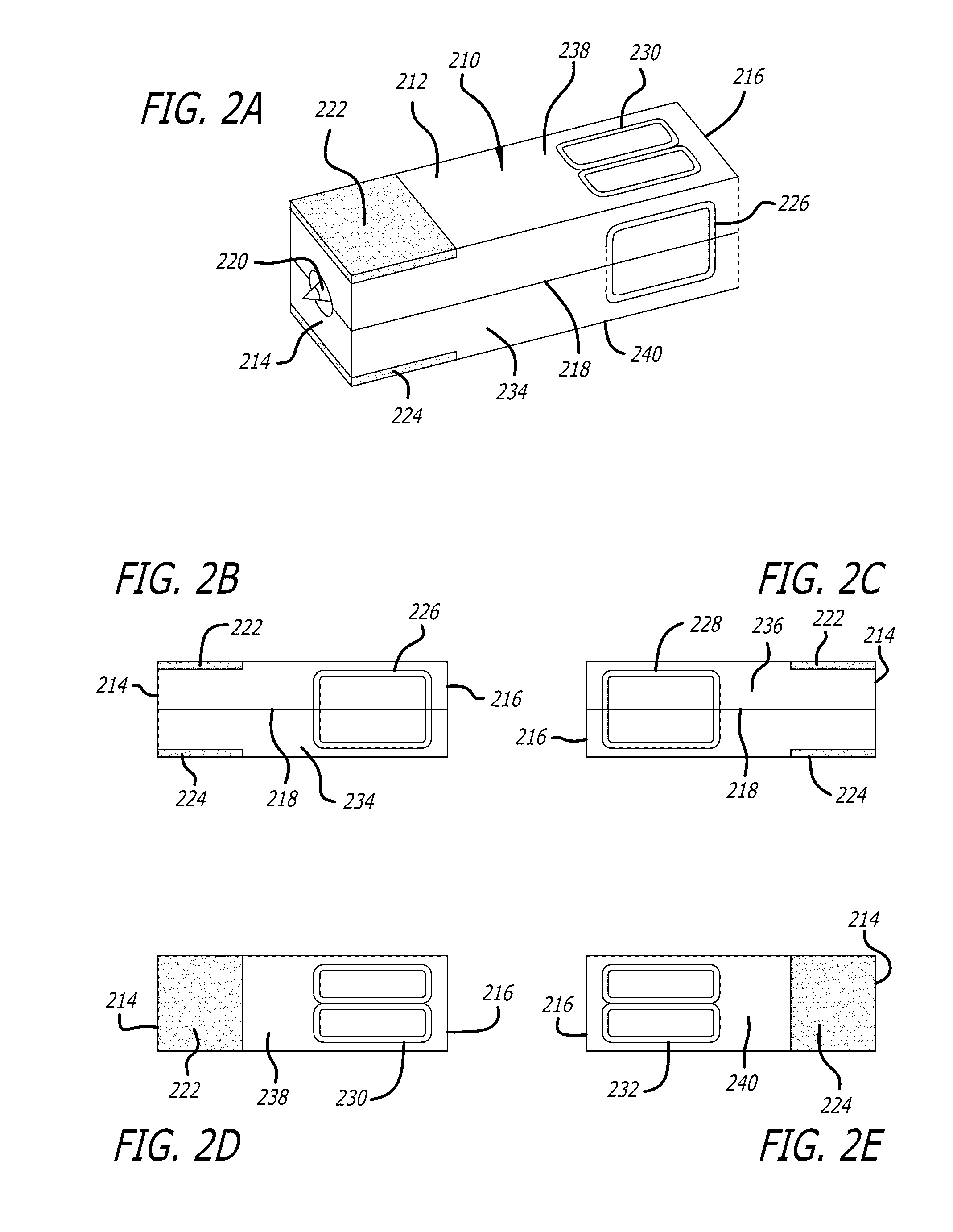
[0055]The Launch craft is accelerated along the launch tube by a Lorentz force generated by the interaction between the transverse direct current (DC) dipole magnetic field 314 and the current flowing through conducting plates 222 and 224 located on sabot 212.

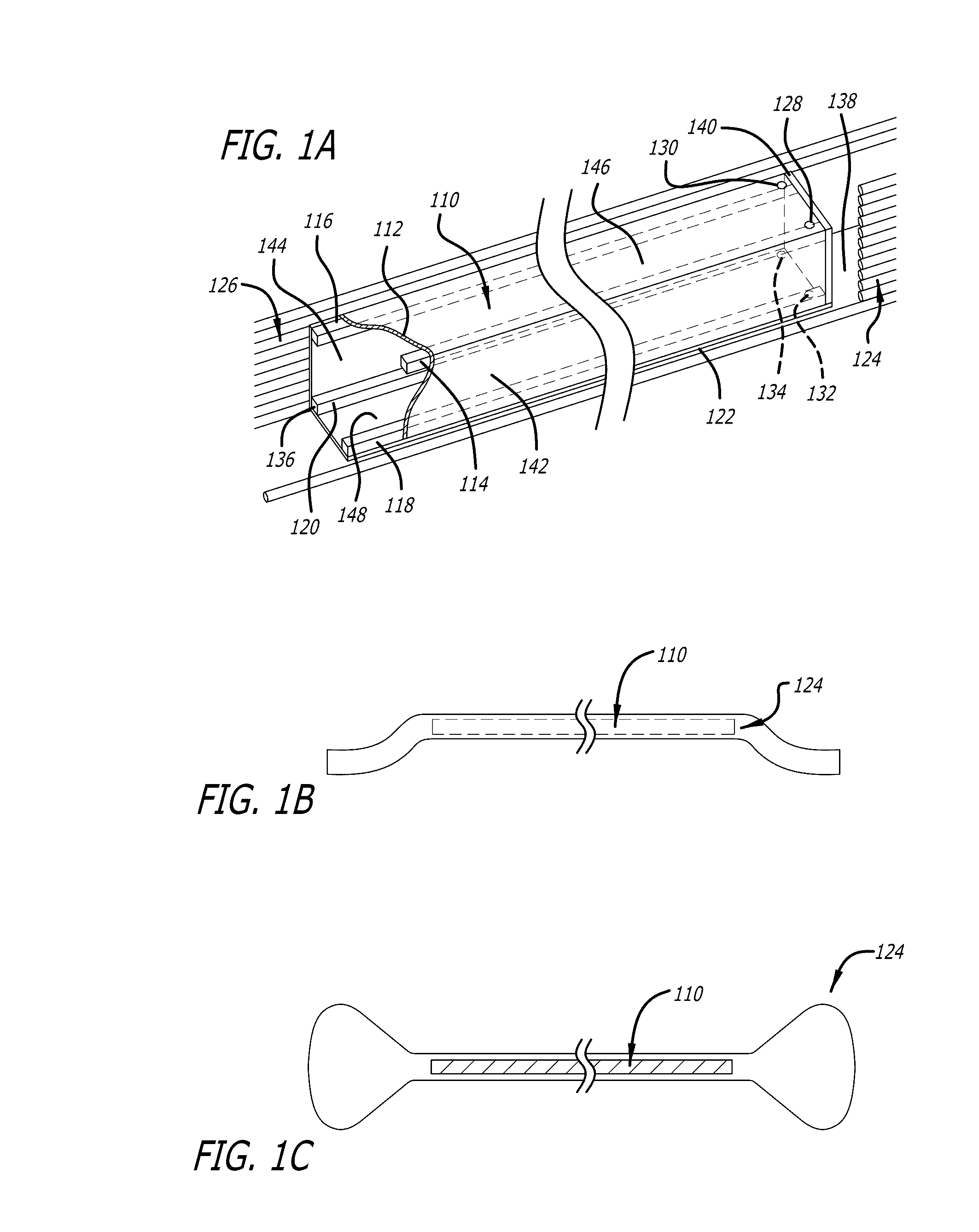
[0056]The DC dipole magnetic field inside launch tube 110 is generated by superconducting (SC) loop assembly 124, 126. The SC cables present in assembly 124, 126 run along the left and right exterior sides of launch tube 110 and are connected together at a predetermined distance and position away from the start 138 and exit 136 ends of launch tube 110 to form a set of long loops that carry continuous, constant DC current. The left and right sides are connected at a sufficient distance from the ends of launch tube 110 so that the desired uniformity of field 314 is not affected.

[0057]In one embodiment, current flows through the right side SC cables of assembly 124, 126 in a direction from start 138 towards exit 136 of la...


PUM


Abstract

A system and method for magnetically launching projectiles or spacecraft includes an electromagnetic launcher including a launch tube, and a launch craft. The launch tube includes electrically conducting rails energized along the length of the rails, and a transverse direct current magnetic field is generated along the launch tube, and upper and lower conductors and loops of conducting material on the launch craft are provided for magnetic levitation, stabilization and propulsion of the launch craft in cooperation with the transverse direct current magnetic field. A transverse direct current magnetic field is applied to the launch tube and the launch craft during launching of the launch craft, and the launch craft is magnetically levitated and stabilized to minimize contact between the launch craft and the launch tube as the launch craft travels within the launch tube.

Description

CROSS-REFERENCES TO RELATED APPLICATIONS[0001]This application is based upon and claims priority from U.S. Provisional Patent Application No. 62 / 146,141, filed Apr. 10, 2015, which is incorporated by reference herein in its entirety.BACKGROUND[0002]This application relates generally to a system and method for electromagnetically launching payloads such as projectiles, launch vehicles, spacecraft, aircraft, missiles, rockets, or the like, and more particularly relates to an electromagnetic launcher, an electromagnetic launch system and a method for electromagnetically launching such payloads that utilizes magnetic levitation, stabilization and propulsion, employing a transverse direct current magnetic field generated in superconducting cables extending along a launch tube.[0003]Electromagnetic launch systems typically are capable of accelerating payloads such as projectiles, launch vehicles, spacecraft, aircraft, missiles or rockets, for example, to high velocities. Electromagnetic l...

Claims


Application Information

Patent Timeline
Patent Type & Authority Applications(United States)
IPC IPC(8): B64G1/00F41B6/00B64G5/00
CPCB64G1/002F41B6/006B64G5/00
Inventor POWELL, JAMES R.
Owner POWELL JAMES R
Why Eureka
Try Eureka