
High temperature and high humidity testing device and high temperature and high humidity testing system

Active Publication Date: 2016-10-13
BOE TECH GRP CO LTD +1
View PDF5 Cites 2 Cited by
  • Summary
  • Abstract
  • Description
  • Claims
  • Application Information

AI Technical Summary

Benefits of technology

The present invention provides a high temperature and high humidity testing device and a high temperature and high humidity testing system that can separately perform high temperature and high humidity test on a display panel without damaging a non-test portion of the display panel. The testing device has a divided test platform with a work area and a non-work area, allowing for separate testing of the under-test portion of the display panel. Additionally, the invention features good sealing property and efficient testing with multiple devices simultaneously. The stable placement of the display panel can also be achieved while preventing damage to the panel.

Problems solved by technology

However, the existing testing method has the following problems; since the whole display panel needs to be put into the test layer, a under-test portion (e.g. a hounding area) and a non-test portion (e.g. a POLL, attachment portion, an IC attachment portion, a display area, etc.) of the display panel are both positioned in the test environment, that is, the test environment may simultaneously influence the under-test portion and the non-test portion.
Moreover, when the non-test portion is damaged in the test process, since the damage is irreparable, the display panel is directly scrapped.

Method used


Image

  • High temperature and high humidity testing device and high temperature and high humidity testing system
  • High temperature and high humidity testing device and high temperature and high humidity testing system
  • High temperature and high humidity testing device and high temperature and high humidity testing system

Examples


first embodiment

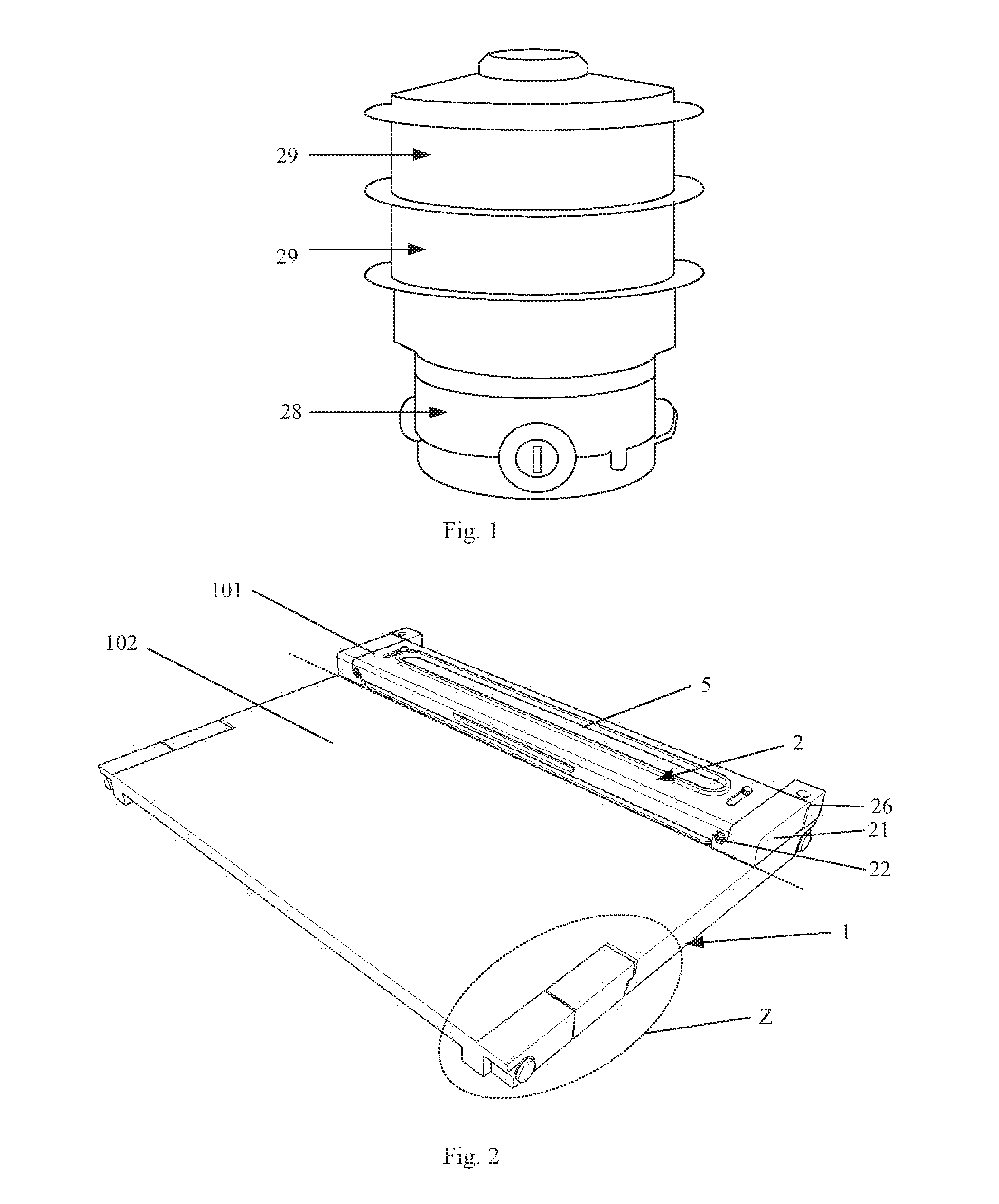
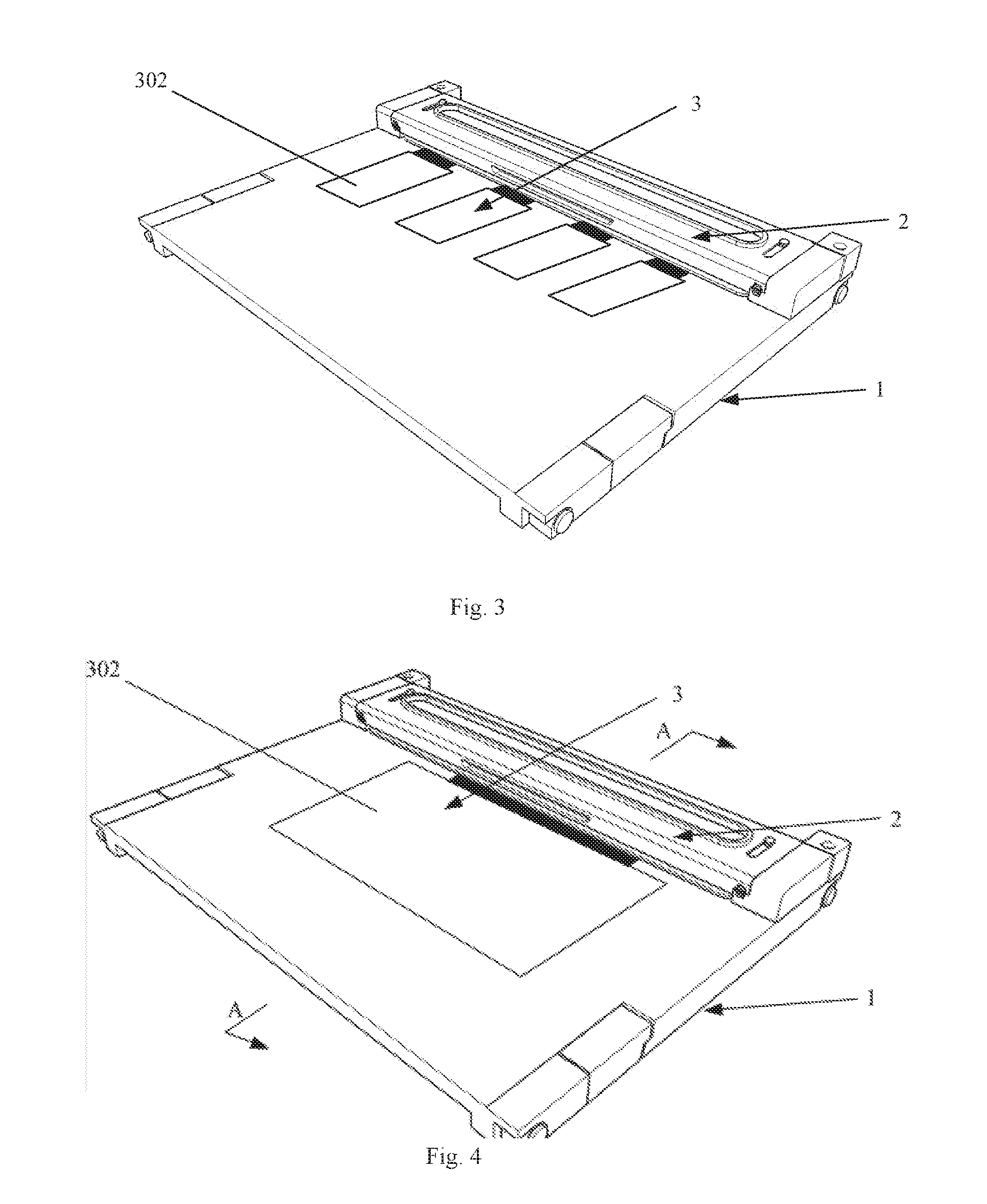
[0067]FIG. 2 is a structural schematic diagram of a high temperature and high humidity testing device according to the first embodiment of the present invention, FIG. 3 is a schematic diagram when the high temperature and high humidity testing device shown in FIG. 2 performs high temperature and high humidity test on small-sized display panels, FIG. 4 is a schematic diagram when the high temperature and high humidity testing device shown in FIG. 2 performs high temperature and high humidity test on large-sized display panels 3, and FIG. 5 is a schematic diagram of a cross section taken along line A-A of FIG. 4. As shown in FIG. 2 to FIG. 5, the high temperature and high humidity testing device includes: a test platform 1 composed of a work area 101 and a non-work area 102, the work area 101 is used for carrying a under-test portion 301 of a display panel 3, and the non-work area 102 is used for carrying a non-test portion 302 of the display panel 3; and a sealing cover 2 arranged ab...

second embodiment

[0092]The second embodiment of the present invention provides a high temperature and high humidity testing system, which includes a gas generating device and at least one high temperature and high humidity testing device, wherein the gas generating device generates high temperature and high humidity gas, the high temperature and high humidity testing device is the one provided in the first embodiment, and for the specific content of the high temperature and high humidity testing device, reference may be made to the description in the first embodiment, which will not be redundantly described herein.


PUM


Abstract

The invention discloses a high temperature and high humidity testing device and a high temperature and high humidity testing system. The high temperature and high humidity testing device comprises: a test platform composed of a work area and a non-work area, the work area is used for carrying a under-test portion of a display panel, and the non-work area is used for carrying a non-test portion of the display panel; and a sealing cover arranged above the work area, wherein the sealing cover and the test platform jointly form a sealed chamber in the work area, the test platform is provided with a gas guide through groove in the work area, and the gas guide through groove is used for delivering high temperature and high humidity gas to the sealed chamber.

Description

FIELD OF THE INVENTION[0001]The present invention relates to the field of display technology, and particularly relates to a high temperature and high humidity testing device and a high temperature and high humidity testing system.BACKGROUND OF THE INVENTION[0002]In order to ensure that display panels can stand the influences of different environments at different latitudes, different regions, different altitudes and the like so that products can still be normally used in different use environments (severe cold regions, low-latitude extremely hot regions, high-humidity regions of coastal cities, high-temperature environments in automobiles and the like), a certain quantity of display panels are extracted in the production process, high temperature and high humidity (a temperature of 100° C. and a humidity of 100%) test is performed on bounding areas of these display panels, and then the tolerance of the products under severe conditions is assessed.[0003]FIG. 1 is a structural schemat...

Claims


Application Information

Patent Timeline
IPC IPC(8): G01N19/10
CPCG01N19/10G02F1/1309G09G3/006G02F2202/00G06F3/00
Inventor JIANG, YANTANG, XIANZHENLU, XIAOMINGLI, DANGONG, XIAOWEIKIM, CHIYOUNG
Owner BOE TECH GRP CO LTD
Features
  • Generate Ideas
  • Intellectual Property
  • Life Sciences
  • Materials
  • Tech Scout
  • Unparalleled Data Quality
  • Higher Quality Content
  • 60% Fewer Hallucinations
Learn More