Attachment apparatus for remote access tools
- Summary
- Abstract
- Description
- Claims
- Application Information
AI Technical Summary
Benefits of technology
Problems solved by technology
Method used
Image
Examples
embodiment 1
[0143]FIG. 19 shows a three axis gimbal (3 DoF), and FIG. 20 shows a spherical roller bearing (3 DoF) that may be used with this variation.
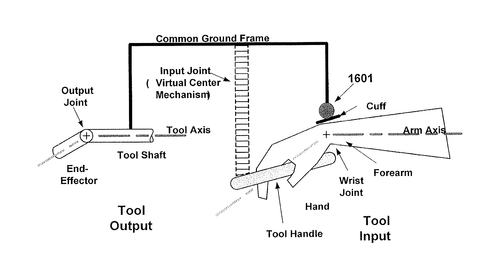
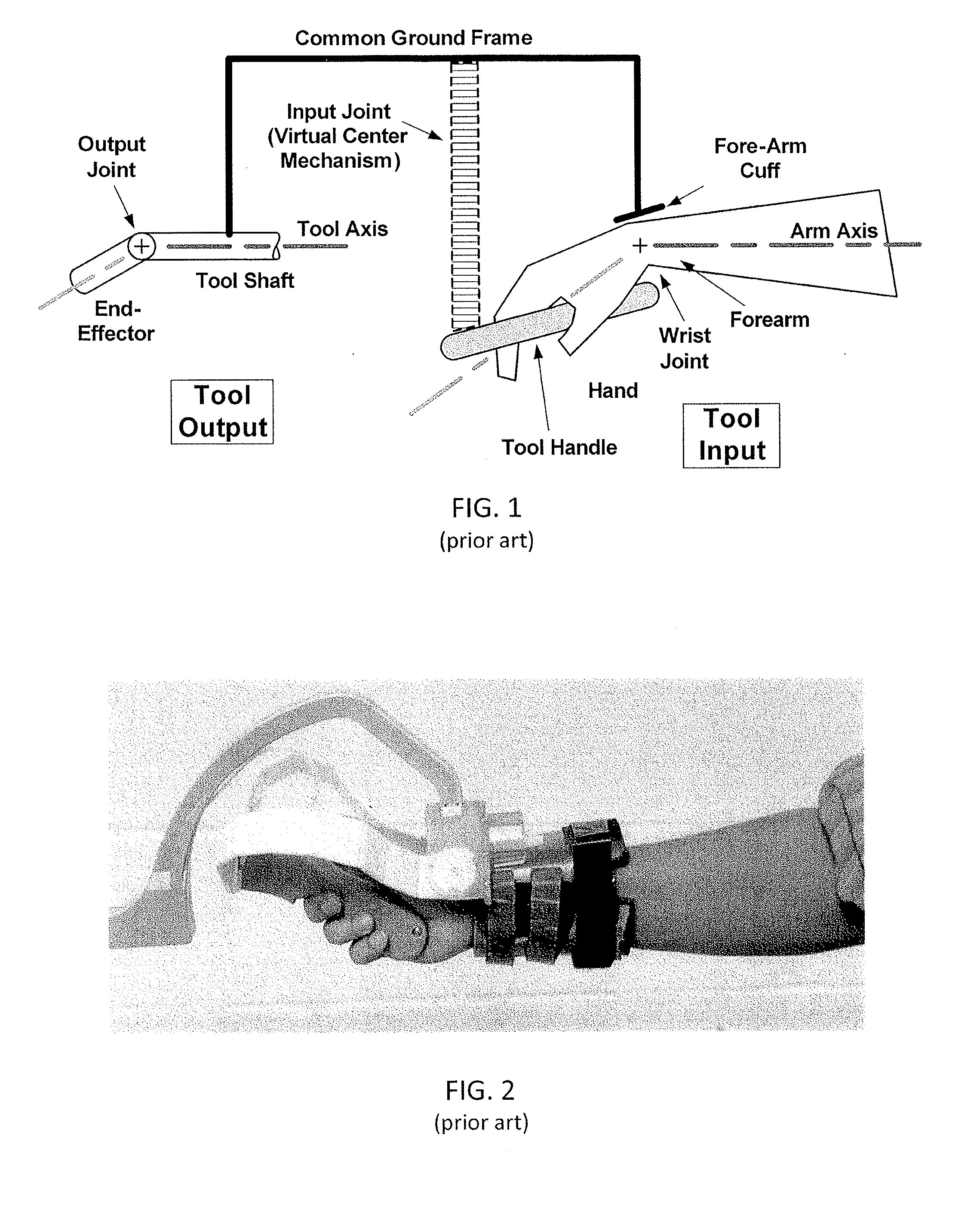
[0144]The forearm attachment assembly as previously described comprises a frame, a connection mechanism, and a cuff. One embodiment that offers 3 DoF is shown above. The apparatus interfaces the frame at the instrument interface (10) and makes a secure rigid attachment to the frame. Within the apparatus, rotation of the forearm about the arm axis and rotation about the hand axis are enabled by the rotation axis (12). This is accomplished in one embodiment but not limited to a keyed track system where one surface slides across another with minimal resistance and is confined by the keying system, in this case a T-slot, to this one axis of rotation. Within the apparatus, the axes identified by (14) and (16) are analogous to the two axes of the wrist itself. These axes offer unhindered rotation during wrist flexion / extension (14) as well as wrist dev...
embodiment 2
[0146]FIG. 21A shows a generic minimal access tool having a frame 2101 including an elongate tool shaft 2100 with a tool axis 2102. A cuff 2108 is formed as part of an inner gimbal 2106. The inner gimbal 2106 and an outer gimbal 2104 and a bearing (shown as a plain bearing configured as a slide 2112) are connected between the frame 2101 and the cuff 2106. In this example, the inner gimbal forms the seat of the cuff and is pivotably connected through a pair of pins to the outer gimbal. The outer gimbal is pivotably connected through a pair of pins to the bearing (slide 2112) and the bearing slides in a track formed by the frame to allow roll rotation. Alternatively a different type of bearing, such as the roll bearing of FIG. 20 may be used. Thus, the body (e.g., forearm) attachment in this example is configured for pitch, yaw and roll DoF, and is arranged so that the roll axis is the same as the tool axis. The tool axis (roll axis), pitch axis of rotation and the yaw axis of rotatio...
embodiment 3
[0148]The forearm attachment assembly shown in FIGS. 22 and 23 offers 2 DoF and is similar to the device previously described in Embodiment 2, however it does not enable the deviation rotation of the wrist (16). In this embodiment, a keyed track system is also present however it utilizes a ball-in-track system where the 2 DoF occur at the same instance as opposed to the stacking of concentric rings in the previous example. This loss of one DoF is not necessarily a detriment to the device but it does restrict some motion that the user may require. To limit one DoF does not mean that this axis, the deviation rotation, could be the only axis to be constrained. As it applies to the minimal access tool device described herein, the rotation typically occurring about the deviation axis is minimal, approximately 5-10 degrees. When this axis is constrained the device can be manipulated in space and fully supported by one hand. This is advantageous because surgeons may choose to introduce and...
PUM
 Abstract
Description
Claims
Application Information
 - R&D
- Intellectual Property
- Life Sciences
- Materials
- Tech Scout
- Unparalleled Data Quality
- Higher Quality Content
- 60% Fewer Hallucinations
Browse by: Latest US Patents, China's latest patents, Technical Efficacy Thesaurus, Application Domain, Technology Topic, Popular Technical Reports.
© 2025 PatSnap. All rights reserved.Legal|Privacy policy|Modern Slavery Act Transparency Statement|Sitemap|About US| Contact US: help@patsnap.com


