Micromechanical device with an actively deflectable element

a micromechanical device and active deflector technology, applied in the direction of microelectromechanical systems, microelectromechanical systems, electrical apparatus, etc., can solve the problems of slow response, further problems, and restricted set of suitable materials, and achieve the effect of tremendously improving manufacturing

Active Publication Date: 2016-10-20
FRAUNHOFER GESELLSCHAFT ZUR FOERDERUNG DER ANGEWANDTEN FORSCHUNG EV
View PDF5 Cites 7 Cited by
  • Summary
  • Abstract
  • Description
  • Claims
  • Application Information

AI Technical Summary

Benefits of technology

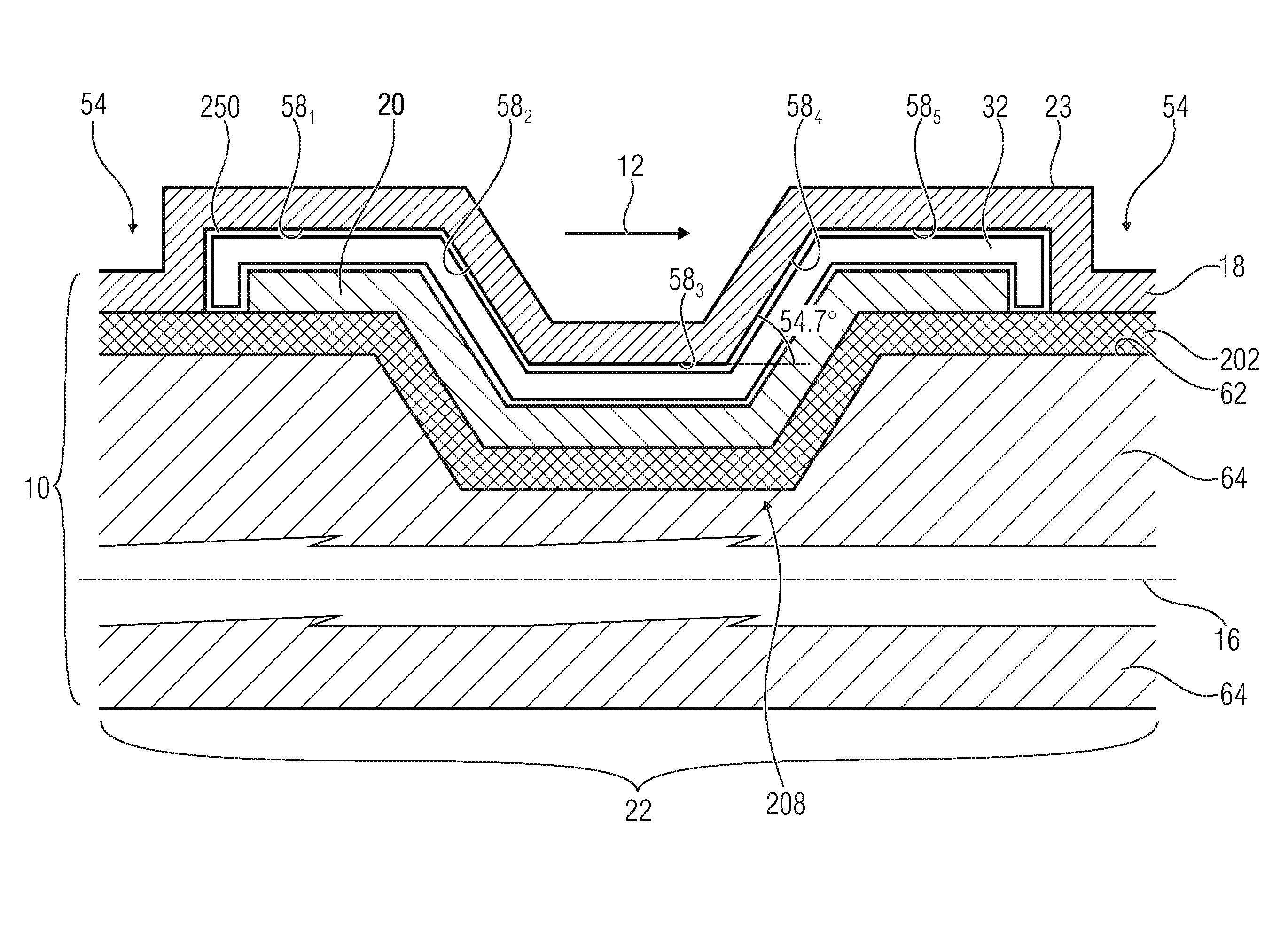
[0017]The bulging-out of the gap of the segments in accordance with the second aspect may be such that the distal layer's surface facing the neutral axis bulges-out in a rounded, angled or stepped manner. In accordance with embodiments associated with the second aspect, the gap between the proximal layer and the distal layer—or the interface between the gap and the distal layer—may be formed of plane portions and ramp portions exclusively, with the plane portions extending in parallel to the

Problems solved by technology

This causes even further problems.
Disadvantageously, however, the response is slow and high temperature differences may be used in order to achieve high deflections.
Beyond this, the set of suitable materials is restricted.
Here, dealing with the useful materials causes a problem sin

Method used


Image

  • Micromechanical device with an actively deflectable element
  • Micromechanical device with an actively deflectable element
  • Micromechanical device with an actively deflectable element

Examples


Embodiment Construction

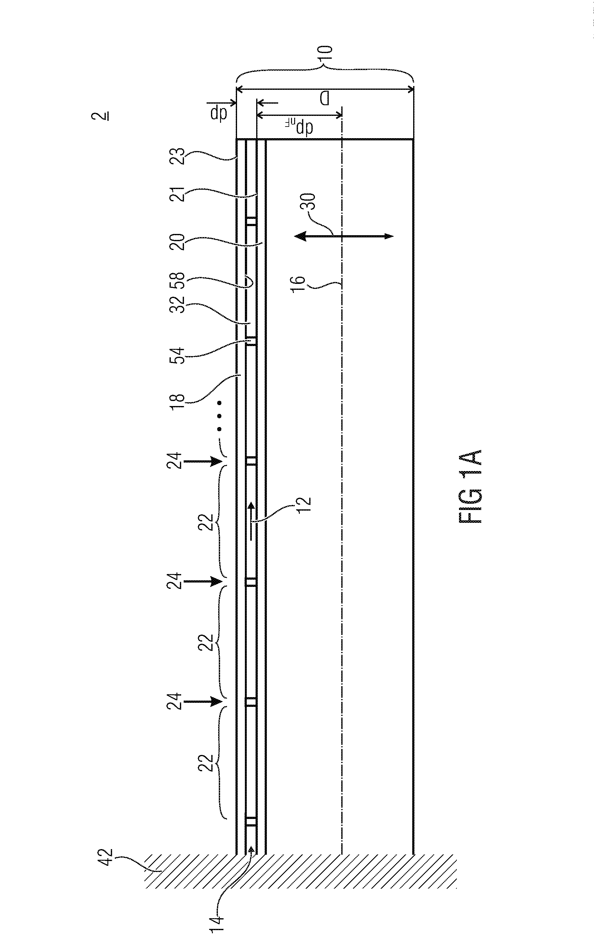
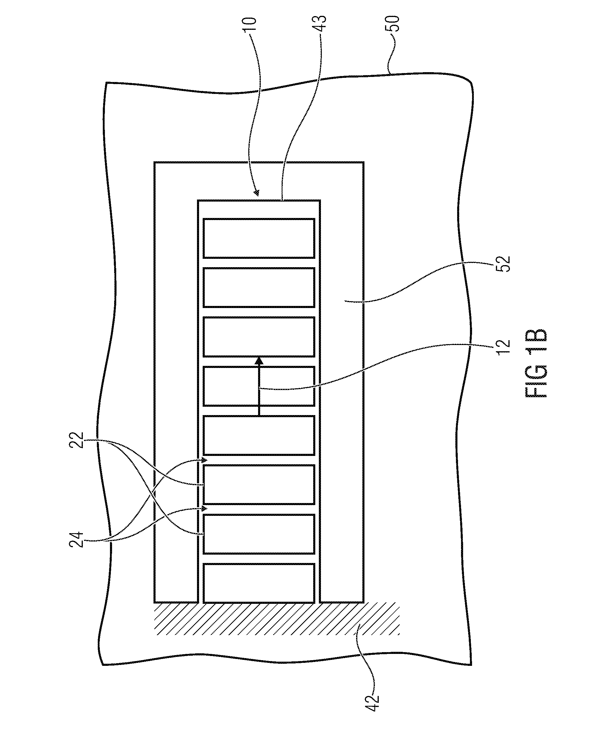
[0051]Before starting with the description of embodiments of the present application in accordance with various aspects of the present application, comparison embodiments of micromechanical devices are described so as to form a reservoir of possible variations in implementing the layer stack which is commonly used in accordance with the subsequently explained embodiments of the various aspects. It is to emphasized, however, that the deflection principle on which these comparison embodiments are based, differs from the principle being the subject of embodiments of the first aspect. Nevertheless, the structural variations of the comparison embodiments as far as the layer stack and the spacers and the gap therebetween is concerned shall be applicable so as to vary embodiments described later with respect to the first aspect, irrespective of the other elements shown in these figures and not occurring in the first aspect's embodiments. With respect to the embodiments of the second and th...


PUM


Abstract

Micromechanical devices include actively deflectable elements. The activation is performed by a layer stack which causes the deflection responsive to attractive forces acting upon the layers of the layer stack.

Description

CROSS-REFERENCE TO RELATED APPLICATIONS[0001]This application claims priority from German Patent Application No. 5206774.2, which was filed on Apr. 15, 2015, and is incorporated herein in its entirety by reference.[0002]The present invention is concerned with a micromechanical device comprising an actively deflectable element.BACKGROUND OF THE INVENTION[0003]Micromechanical devices having a deflectable element such as a cantilever or membrane are used in a multitude of technical fields, such as in spatial light modulators or in projectors for beam deflection, just to mention a few examples.[0004]Primarily, electrostatic attraction used in micro and nano actuators as the principle for deflection. Mostly, different electrostatic potentials are applied to a deflectable element and a static electrode so that by aid of an electrostatic attraction developing therebetween, a deflection is caused. The force is indirectionally proportional to the square of the distance between the deflectabl...

Claims


Application Information

Patent Timeline
IPC IPC(8): B81B3/00
CPCB81B3/0021B81B2201/032B81B2203/0127B81B2203/0118B81B3/0094
Inventor GAUDET, MATTHIEUSCHIMMANZ, KLAUSSTOLZ, MICHAELLANGA, SERGIUCONRAD, HOLGERKAISER, BERT
Owner FRAUNHOFER GESELLSCHAFT ZUR FOERDERUNG DER ANGEWANDTEN FORSCHUNG EV
Why Eureka
Try Eureka