Cvt transmission

a transmission and cvt technology, applied in the direction of transmission elements, belts/chains/gearrings, transmission control, etc., can solve the problem of large range overlap and achieve the effect of improving the driving comfort of cvt transmission

Inactive Publication Date: 2016-10-20
SCHAEFFLER TECH AG & CO KG
View PDF2 Cites 2 Cited by
  • Summary
  • Abstract
  • Description
  • Claims
  • Application Information

AI Technical Summary

Benefits of technology

[0007]The above-identified object is fulfilled in the case of a CVT transmission having a start-up element, a variator, and having a direct-shift stage for switching between a first operating range (low) and a second operating range (high), by letting a maximum transmission ratio of the second operating range (high) correspond to a minimum transmission ratio of the first operating range (low). With conventional dual-range CVT transmissions, a relatively large overlap of the two transmission ratio ranges is necessary to enable convenient implementation of switching between ranges. However, such a large range overlap is achieved at the expense of an efficiency-optimized variator ratio spread in variator operation. By synchronizing the maximum transmission ratio of the second operating range with the minimum transmission ratio of the first operating range according to the present invention, it is possible to improve the efficiency of the CVT transmission having the direct-shift stage.

Problems solved by technology

However, such a large range overlap is achieved at the expense of an efficiency-optimized variator ratio spread in variator operation.

Method used


Image

  • Cvt transmission
  • Cvt transmission
  • Cvt transmission

Examples


Embodiment Construction

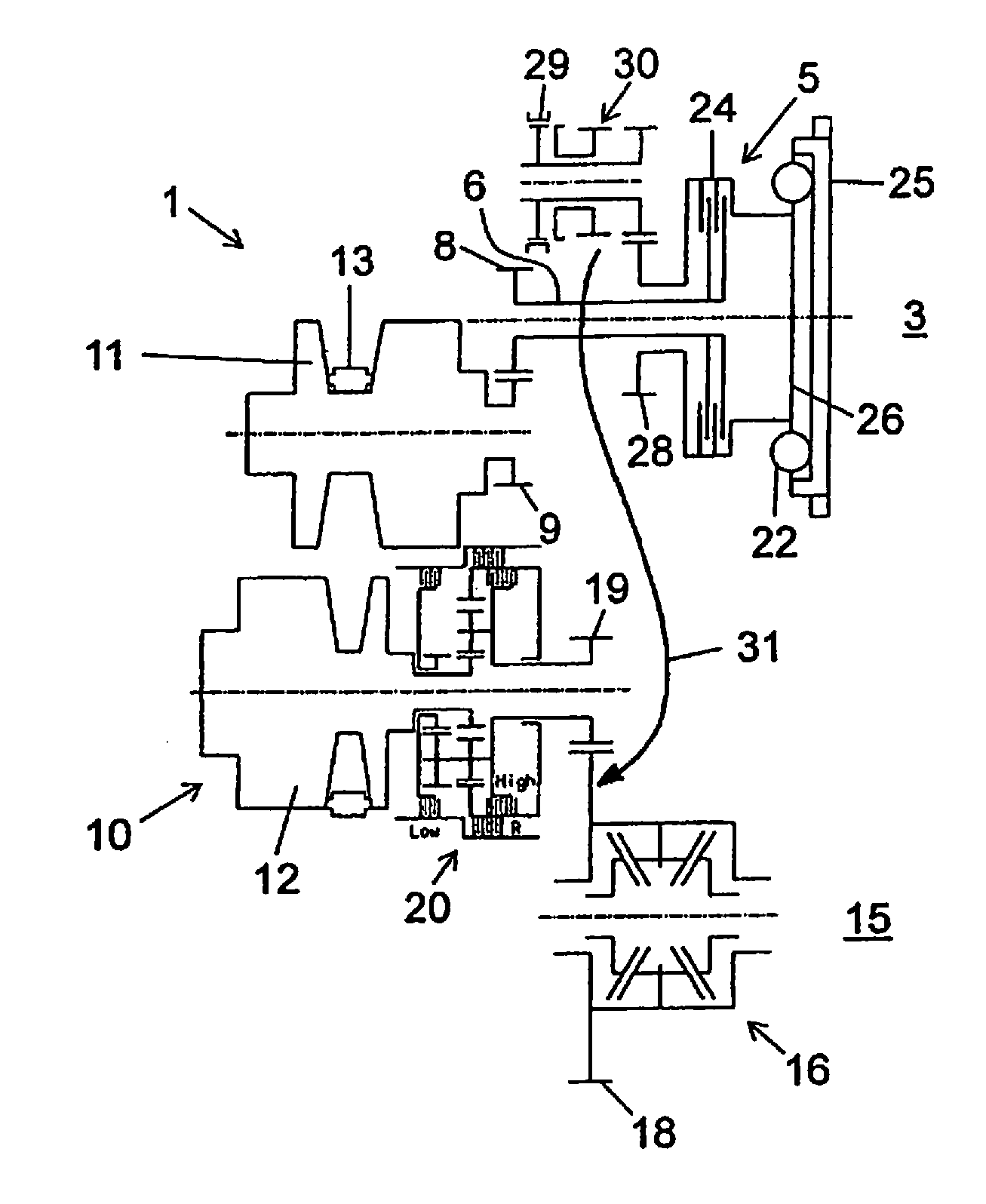
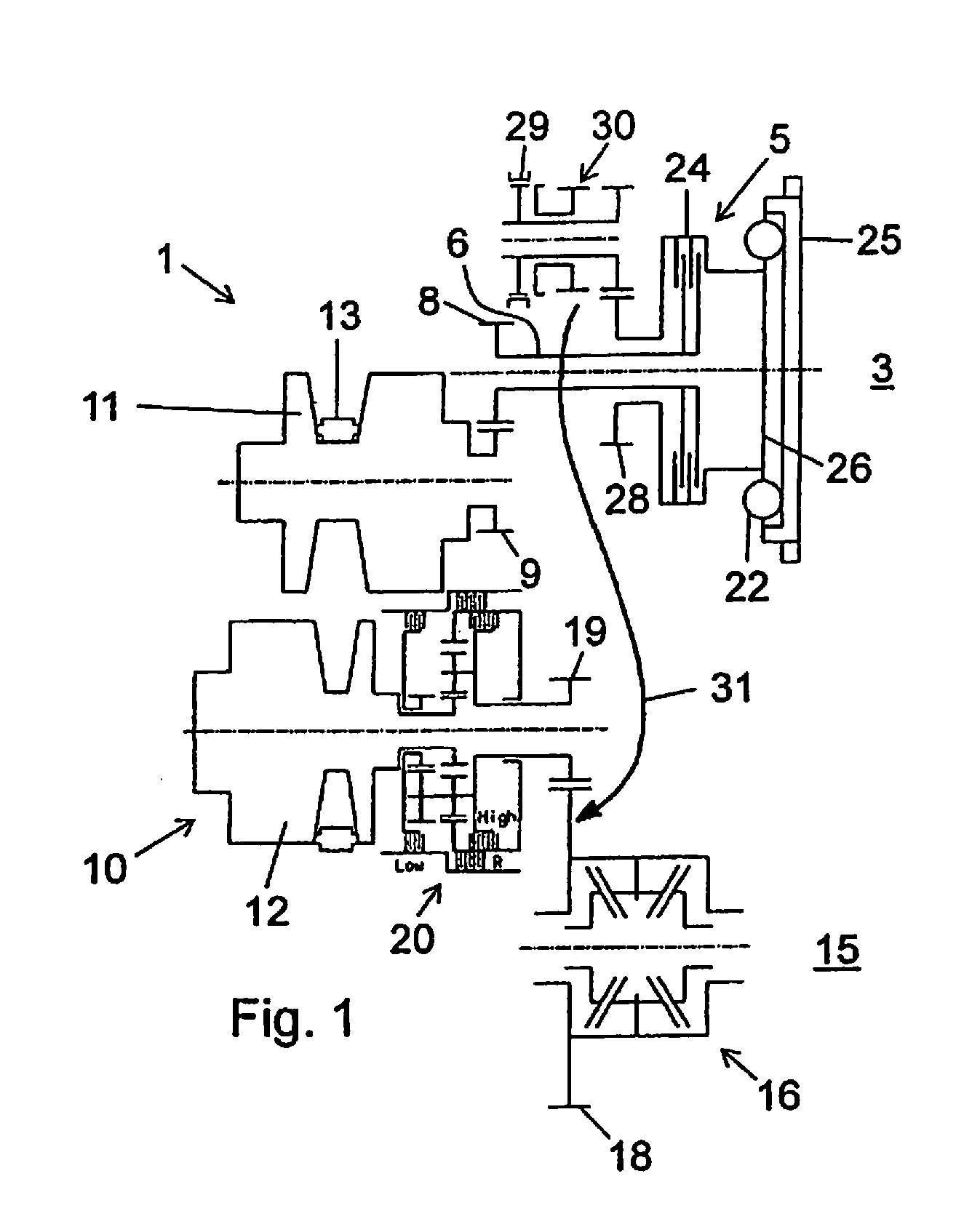
[0024]FIGS. 1 and 2 show different views of a simplified representation of a CVT drive train 1 according to the present invention. The CVT drive train 1 includes an input drive 3. The input drive is, for example, a combustion machine, which is also referred to as an internal combustion engine when used in a motor vehicle. The CVT drive train 1 is used in motor vehicles.

[0025]A start-up element 5 makes it possible to move the motor vehicle off. A torque is transmitted from the input drive 3 to a start-up output part 6 through the start-up element 5. The start-up output part 6 is connected to a variator input of a variator 10 through a gear stage having a gear 8 and a gear 9.

[0026]The variator 10 includes a conical disk set 11 on the drive side and a conical disk set 12 on the output side. The two conical disk sets 11, 12 are coupled with each other by an endless torque-transmitting means 13, which is only shown generally. The endless torque-transmitting means 13 can be, for example, ...


PUM


Abstract

A CVT transmission including a start-up element, a variator, and a direct-shift stage for switching between a first operating range (low) and a second operating range (high). A maximum transmission ratio of the second operating range (high) corresponds to a minimum transmission ratio of the first operating range (low). The transmission ratio ranges are arranged so that the marginal variator transmission ratio ranges, which constitute low-efficiency ranges, are not used.

Description

CROSS-REFERENCE TO RELATED APPLICATION[0001]This application is the U.S. national phase application under 35 U.S.C. §371 of International Application Serial No. PCT / DE2014 / 200661, having an international filing date of 28 Nov. 2014, and designating the United States, which claims priority based upon German Patent Application No. DE 10 2013 225 264.1, filed on 9 Dec. 2013, the entire contents of each of which applications are hereby incorporated by reference herein to the same extent as if fully rewritten.BACKGROUND OF THE INVENTION[0002]1. Field of the Invention[0003]The present invention relates to a CVT transmission having a start-up element, a variator, and having a direct-shift stage for switching between the first operating range (low) and a second operating range (high). In addition, the present invention relates to a method for operating such a CVT transmission.[0004]2. Description of the Related Art[0005]The term CVT refers to a stepless transmission; the letters CVT stand f...

Claims


Application Information

Patent Timeline
Patent Type & Authority Applications(United States)
IPC IPC(8): F16H37/02F16H61/02F16H61/662F16H37/08
CPCF16H37/022F16H37/082F16H2200/2005F16H61/662F16H61/0265
Inventor WALTER, BERNHARD
Owner SCHAEFFLER TECH AG & CO KG
Why Eureka
Try Eureka