Infant bed attachment system

a technology for sleeping surfaces and attachment systems, which is applied in the field of infant sleeping surface attachment systems, can solve the problems of difficult visibility through the hood, inability to monitor the vital signs of the baby, and limited use of sleeping surfaces, etc., and achieve the effect of facilitating vital signs monitoring

Inactive Publication Date: 2016-10-27
KONINKLJIJKE PHILIPS NV
View PDF2 Cites 11 Cited by
  • Summary
  • Abstract
  • Description
  • Claims
  • Application Information

AI Technical Summary

Benefits of technology

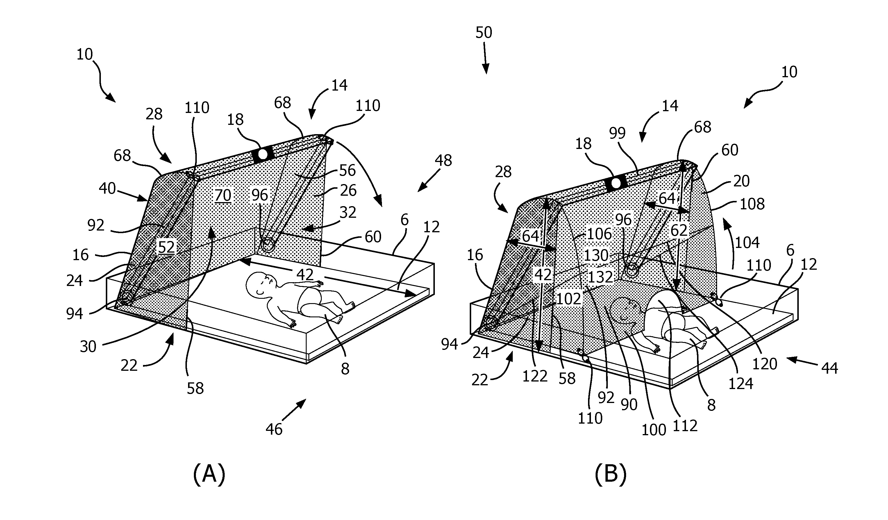
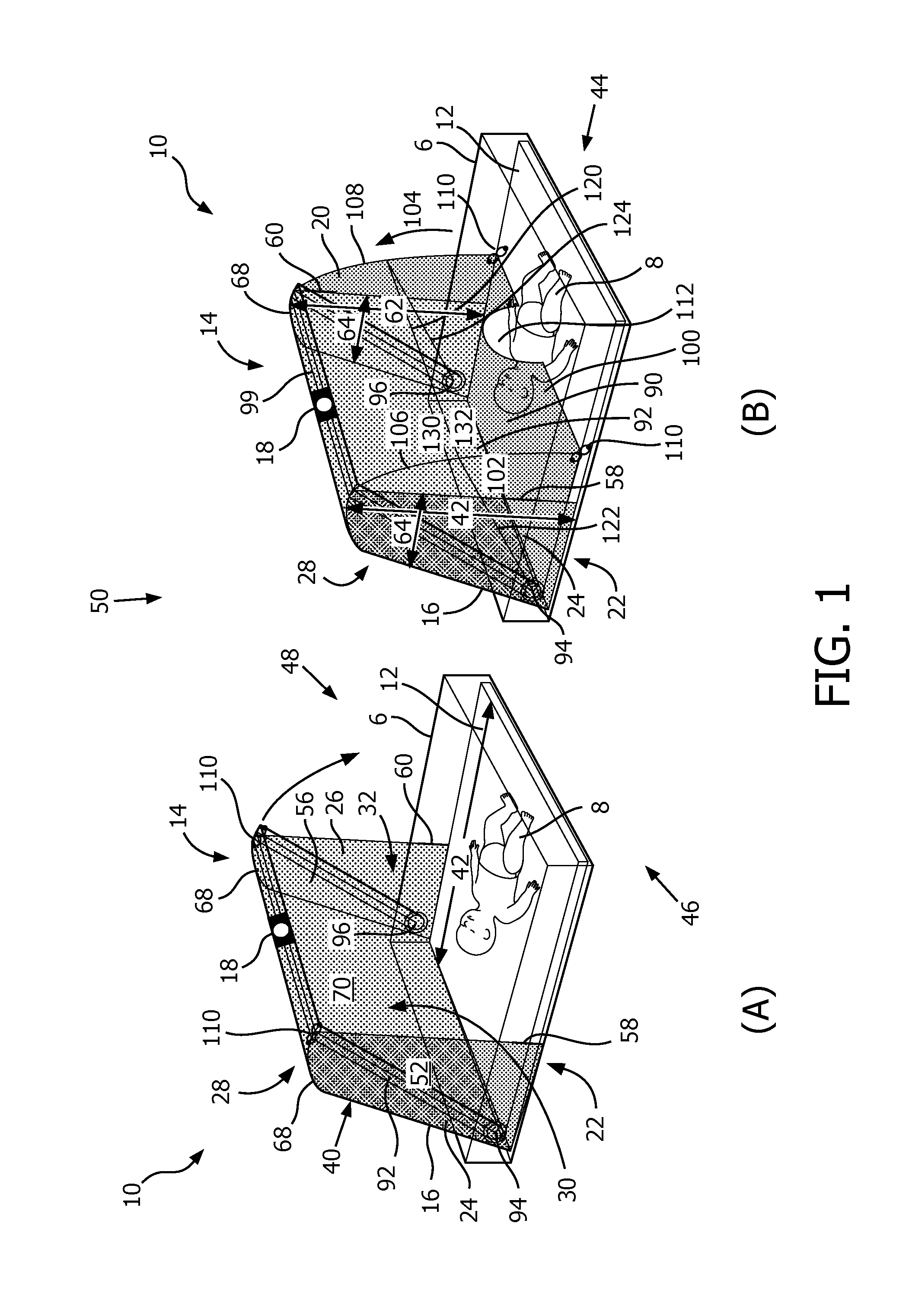
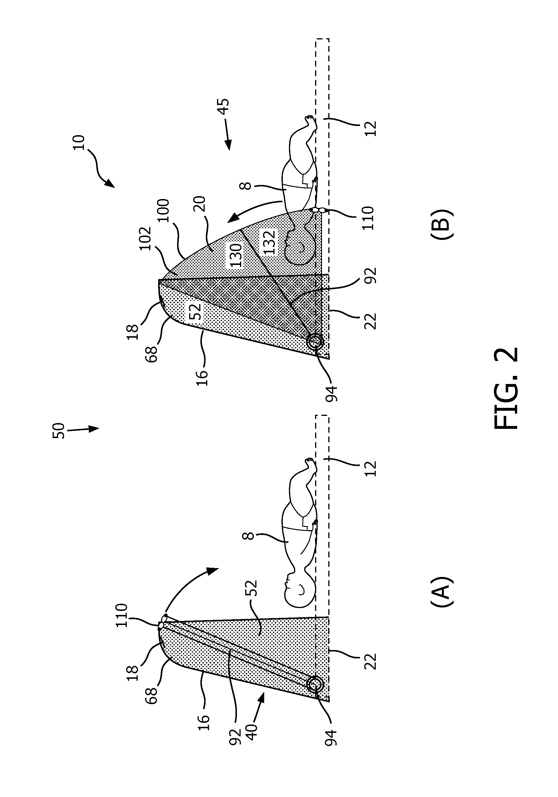
[0006]Another aspect of the present disclosure relates to a method for facilitating vital signs monitoring of, and / or delivering oxygen to, an infant laying on an infant sleeping surface with an infant sleeping surface attachment system. The system comprises a hood and a cover portion. The hood comprises a fixed portion and a mounting apparatus. The method comprises forming a cavity with the fixed portion that is held engaged in a fixed position relative to the infant sleeping surface. The cavity has an open mouth formed in part by the infant sleeping surface. The method comprises engaging a vital signs monitoring device with the mounting apparatus. The mounting apparatus is coupled to the fixed portion inside the cavity. The mounting apparatus is configured to carry the vital signs monitoring device so the vital signs monitoring device has a view of the infant sleeping surface. The method comprises movably coupling the cover portion with the fixed portion such that the cover portion moves with respect to the fixed portion between a retracted position and a closed position. In the closed position, the cover portion covers the open mouth of the cavity. In the retracted position, the cover portion permits physical access to the cavity.

Problems solved by technology

Non-invasive monitoring methods minimize risks associated with invasive monitoring but their use is limited.
There are several constraints on this placement due to NICU equipment, activities, and procedures.
After multiple uses and subsequent cleanings, the surface of the oxyhood is typically scratched and damaged, which makes visibility through the hood very difficult and makes camera based monitoring impossible.

Method used


Image

  • Infant bed attachment system
  • Infant bed attachment system
  • Infant bed attachment system

Examples


Embodiment Construction

[0015]As used herein, the singular form of “a”, “an”, and “the” include plural references unless the context clearly dictates otherwise. As used herein, the statement that two or more parts or components are “coupled” shall mean that the parts are joined or operate together either directly or indirectly, i.e., through one or more intermediate parts or components, so long as a link occurs. As used herein, “directly coupled” means that two elements are directly in contact with each other. As used herein, “fixedly coupled” or “fixed” means that two components are coupled so as to move as one while maintaining a constant orientation relative to each other.

[0016]As used herein, the word “unitary” means a component is created as a single piece or unit. That is, a component that includes pieces that are created separately and then coupled together as a unit is not a “unitary” component or body. As employed herein, the statement that two or more parts or components “engage” one another shal...


PUM


Abstract

The present disclosure pertains to an infant sleeping surface attachment system configured to facilitate vital signs monitoring of, and/or delivering oxygen to, an infant laying on an infant sleeping surface. The system is configured to engage a vital signs monitoring device so the vital signs monitoring device has a view of the infant sleeping surface. The system has a retracted position and a closed position. The closable cavity has a mounting apparatus for engaging a vital signs monitoring device inside the cavity. The mounting apparatus is configured such that the vital signs monitoring device maintains a field of view on a region of interest and minimizes the possibility of occluding the view of the vital signs monitoring device. Thus, it is possible to continuously monitor of the infant from inside the cavity without having any glass/plastic material (e.g., the wall of a typical oxyhood) obstructing the field of view.

Description

BACKGROUND[0001]1. Field[0002]The present disclosure pertains to an infant sleeping surface attachment system configured to engage a vital signs monitoring device so the vital signs monitoring device has a view of the infant sleeping surface. When necessary, a flexible and moveable portion of the infant sleeping surface attachment system is configured to close to deliver oxygen to an infant laying on the infant sleeping surface without obstructing the field of view of the vital signs monitoring device.[0003]2. Description of the Related Art[0004]Typically, neonatal intensive care units (NICU) are fragile environments consisting of sick preterm and term neonatal infants. Vital signs monitoring of these neonates is usually done using invasive methods with attached probes, sensors, electrodes, and / or other devices. Non-invasive monitoring methods minimize risks associated with invasive monitoring but their use is limited. Camera based monitoring is one such method. A camera may be plac...

Claims


Application Information

Patent Timeline
Patent Type & Authority Applications(United States)
IPC IPC(8): A47D15/00A61G13/10A61G10/04A61B5/11A61B5/113A61G11/00A61B5/00
CPCA47D15/00A61G11/006A61G13/101A61G10/04A61B5/1128A61B5/1135A61B5/0077A61B5/1079A61B5/11A61G11/009B62B9/14
Inventor POTHEN, MANJU CATHERINEKAPIL, SHIVI
Owner KONINKLJIJKE PHILIPS NV
Why Eureka
Try Eureka