Braking system for towed vehicles

a braking system and towed vehicle technology, applied in the field of towed vehicles, can solve problems such as difficulty in providing effective braking for air seeders using conventional towed vehicle braking systems, control issues, and unloading implement trains can still be hazardous, and achieve the effects of facilitating bushing replacement, dampening the brake action, and simplifying maintenan

Active Publication Date: 2016-10-27
BOURGAULT INDS
View PDF1 Cites 15 Cited by
  • Summary
  • Abstract
  • Description
  • Claims
  • Application Information

AI Technical Summary

Benefits of technology

[0010]The towed vehicle apparatus of the present disclosure provides a smoothly functioning sliding hitch tongue that serves to operate a master cylinder for actuating a brake cylinder for use with very large towed vehicles with weights in excess of 50 or 60 tons. Maintenance is simplified by having the master cylinder fully exposed, and by providing a removable bushing section that facilitates bushing replacement.
[0011]In a second embodiment the present disclosure provides a braking system for a towed vehicle, the towed vehicle including a hitch tongue adapted for connection at a front end thereof to a towing vehicle. The system comprises an extendable master cylinder comprising a pressurized fluid port at a first end thereof and a reservoir port at a second end thereof, the master cylinder mounted in the hitch tongue such that a rearward force urging the hitch tongue rearward exerts a corresponding force on the master cylinder and forces pressurized braking fluid out of a pressurized fluid port of the master cylinder. A brake conduit connects the pressurized fluid port of the master cylinder to an inlet of a brake cylinder, the brake cylinder operative to exert a braking force on wheels of the towed vehicle when pressurized braking fluid enters the inlet thereof. A first sequence valve in the brake conduit is configured to prevent flow through the brake conduit until pressurized braking fluid at the inlet thereof reaches a first pressure, and to open a path from the inlet thereof to an outlet thereof to allow braking fluid to flow through the brake conduit when pressurized braking fluid at the inlet thereof exceeds the first pressure. A first restrictive orifice is present in the brake conduit between the outlet of the first sequence valve and the inlet of the brake cylinder. A reversing valve in the brake conduit is configured such that when a reversing control is in a braking position, the reversing valve provides a path from the inlet thereof to an outlet thereof such that pressurized braking fluid flows through the brake conduit, and when the reversing control is in a reversing position the reversing valve closes the path from the inlet thereof to the outlet thereof, and provides a path from the outlet thereof to a fluid reservoir such that pressurized braking fluid at the inlet of the brake cylinder is relieved to a fluid reservoir. A first return conduit is connected at one end to the brake conduit between the first restrictive orifice and the inlet of the brake cylinder, and is connected at an opposite end thereof to the pressurized fluid port of the master cylinder, and a first check valve in the first return conduit is configured to allow braking fluid flow from the inlet of the brake cylinder to the pressurized fluid port of the master cylinder, and to prevent braking fluid flow from the pressurized fluid port of the master cylinder to the inlet of the brake cylinder. A second return conduit connects the fluid reservoir to the pressurized fluid port of the master cylinder, and a second check valve in the second return conduit is configured to allow braking fluid flow from the fluid reservoir to the pressurized fluid port of the master cylinder, and to prevent braking fluid flow from the pressurized fluid port of the master cylinder to the fluid reservoir. A reservoir conduit connects the reservoir port of the master cylinder to the fluid reservoir.
[0012]The braking system prevents braking during gradual slowing down of the towing vehicle, or on shallow inclines, provides dampening of the brake action, and allows for the operator to reverse the towed vehicle without the brakes being activated. Emergency stopping and dampening of sliding movement of the hitch tongue are provided as well.
[0014]The braking system provides smooth braking action by sensing what the towed vehicle is doing, and applying brake force as required in response. The system requires no moving parts that can be damaged by large forces encountered where, for example the product cart is towed between the tractor and the furrow opener implement.

Problems solved by technology

Braking systems are required for towed vehicles such as trailers and the like where the brakes of the towing vehicle are not sufficient to provide adequate braking for the added weight of the towed vehicle.
A train including a product cart, furrow opener implement, and extra fertilizer tank can outweigh the towing tractor by over 1.5 times when empty and when this heavy train is being towed at high transport speeds, it can cause control issues.
Due to the heavy weight of the unloaded train and the high transport speeds that can be achieved, an unloaded implement train can still be hazardous.
Because of the heavy weight of the cart and the considerable distance between the tractor as a braking power source and the cart, providing effective braking for air seeders using conventional towed vehicle braking systems is problematic.

Method used


Image

  • Braking system for towed vehicles
  • Braking system for towed vehicles
  • Braking system for towed vehicles

Examples


Embodiment Construction

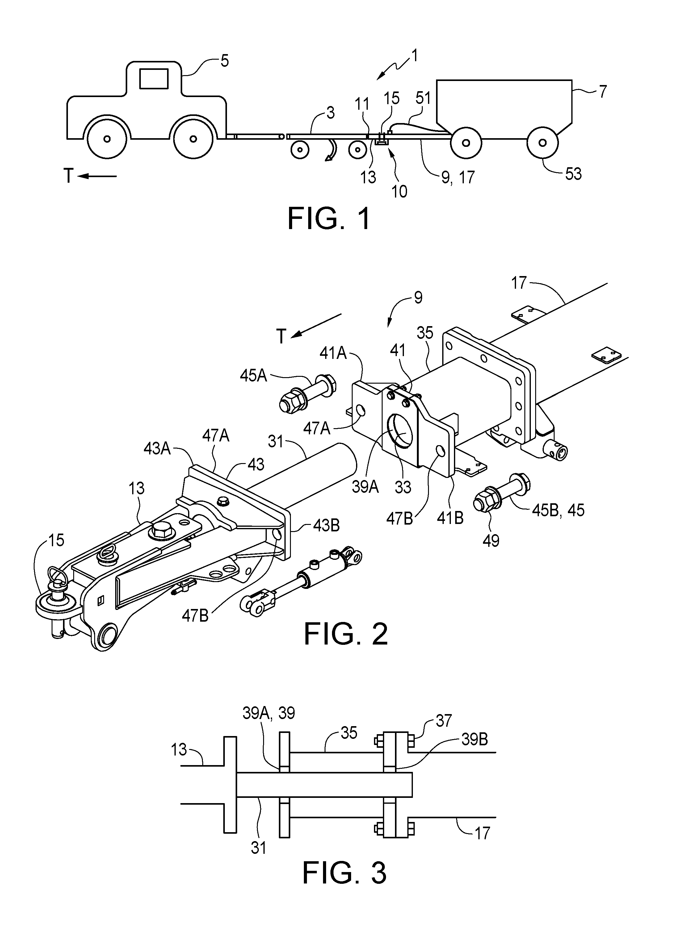
[0031]FIG. 1 schematically illustrates a common configuration of an air seeder 1 where the furrow opener implement 3 is towed behind the tractor 5 and the product cart 7 is towed behind the furrow opener implement 3.

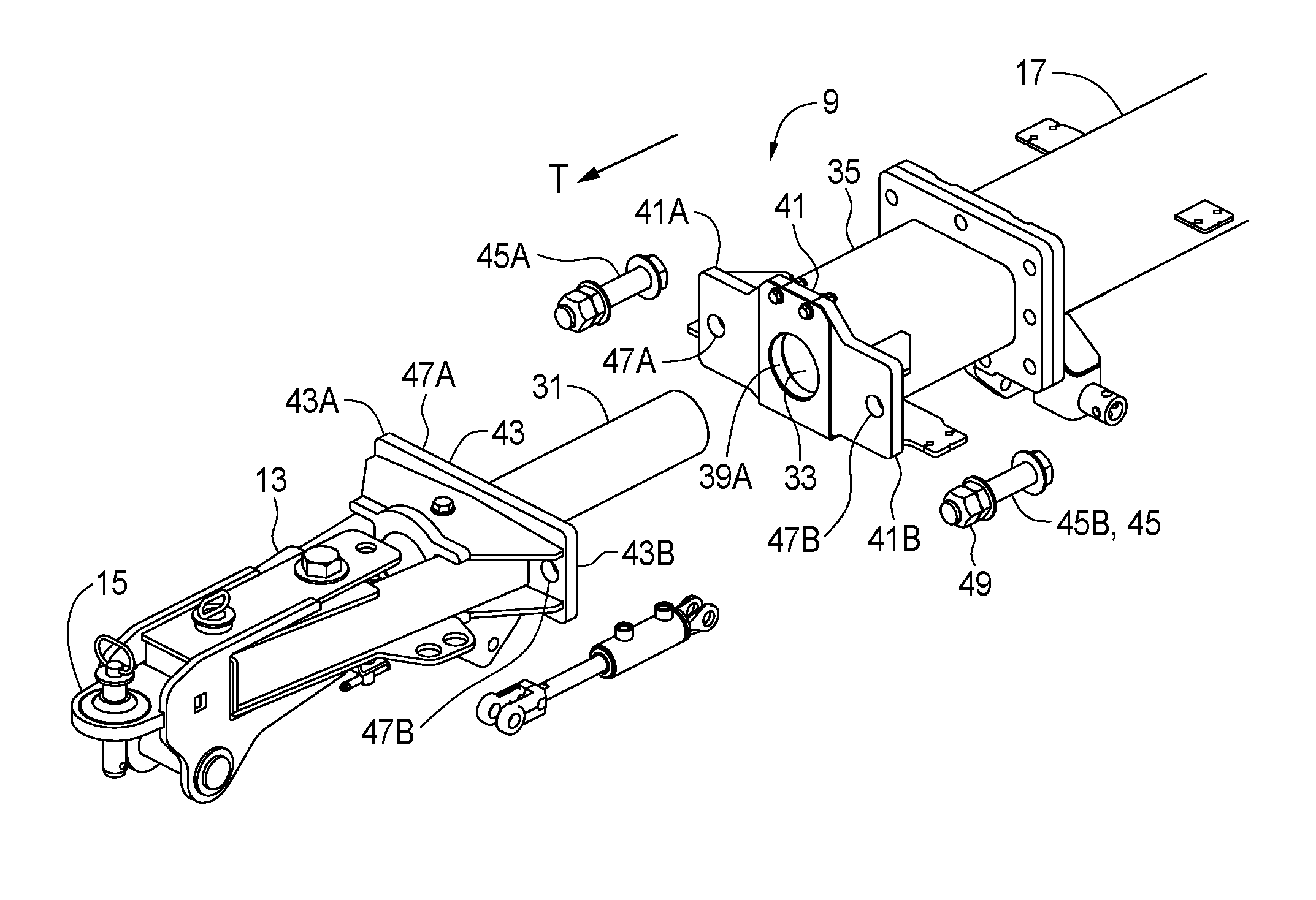
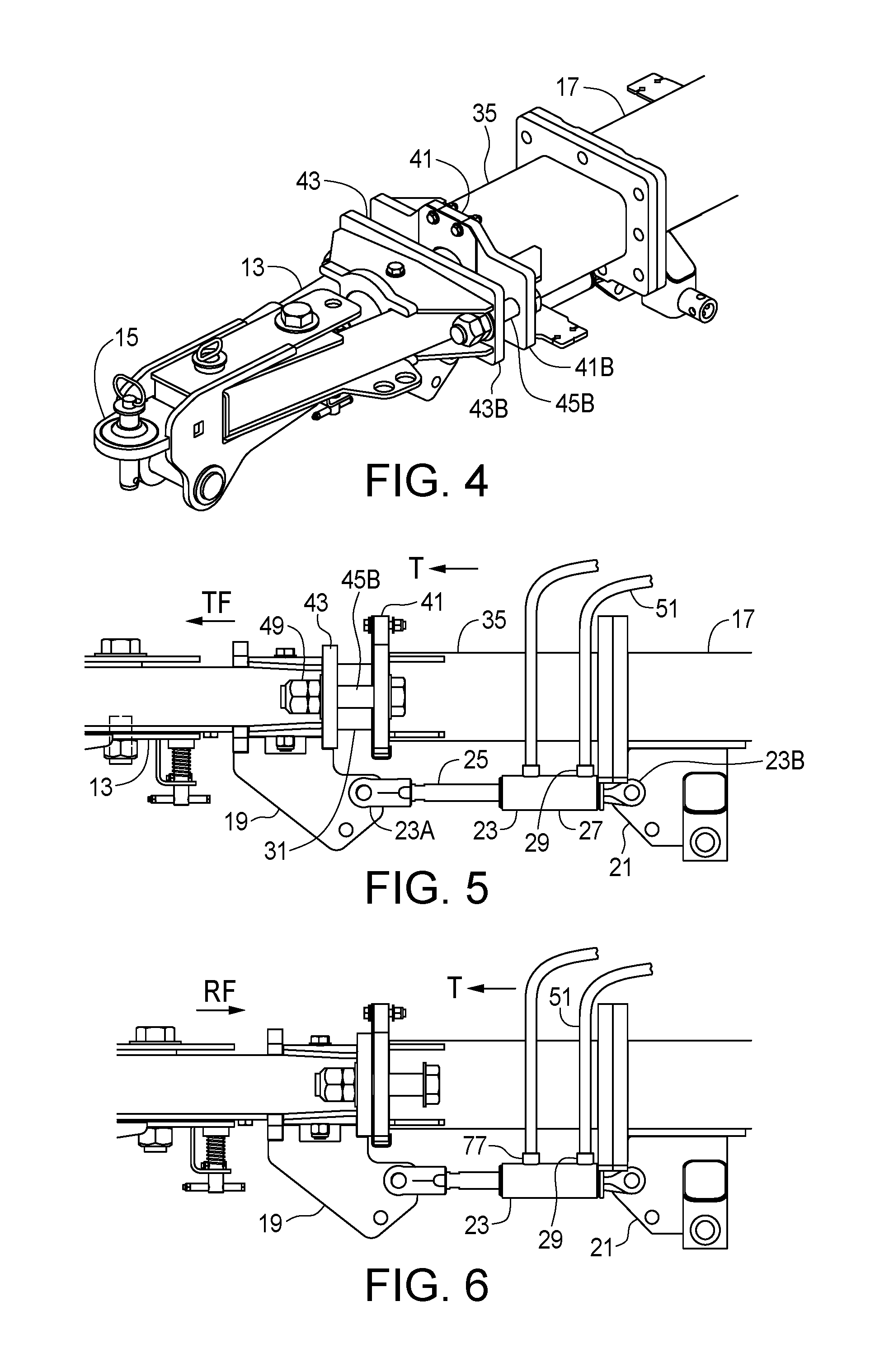
[0032]An embodiment of a towed vehicle apparatus 10 of the present disclosure is installed on the hitch tongue 9 that connect the towed vehicle, here being the product cart 7, to the tow hitch 11 of a towing vehicle, here being the furrow opener implement 3, for movement in an operating travel direction T. As illustrated in FIGS. 2-6, the hitch tongue 9 comprises a front tongue member 13 with a front end 15 thereof configured to engage the tow hitch 11, and a rear tongue member 17 attached to a front end of the product cart 7.

[0033]In the illustrated hitch tongue 9 the front tongue member 13 is telescopically connected to the rear tongue member 17 such that the front tongue member 13 is movable in the operating travel direction T with respect to the rear tongue member 17...


PUM


Abstract

A towed vehicle hitch tongue includes movably connected front and rear tongue members, and a fully exposed master cylinder connected at opposite ends thereof to the tongue members such that a rearward force urging the front tongue member toward the rear tongue member forces pressurized braking fluid out of a port thereof into a braking circuit configured to exert a braking force. The braking circuit prevents braking until the rearward force warrants braking, provides dampening of the brake action, allows the towed vehicle to reverse, and can provide emergency stopping and dampening of movement of the hitch tongue. Instead of using movable front and rear tongue members, sensors can detect what the towed vehicle is doing, and apply appropriate braking force in response.

Description

CROSS-REFERENCE TO RELATED APPLICATION[0001]This application claims priority to and benefit of Canadian Application Serial No. 2889117 filed Apr. 22, 2015, the contents of which are incorporated herein in its entirety for all purposes.FIELD OF THE INVENTION[0002]This disclosure relates to the field of towing vehicles and in particular a braking system for towed vehicles.BACKGROUND[0003]Braking systems are required for towed vehicles such as trailers and the like where the brakes of the towing vehicle are not sufficient to provide adequate braking for the added weight of the towed vehicle.[0004]Surge or inertial braking systems use the force exerted by the towed vehicle on the towing vehicle through the tow hitch apparatus to activate brakes on the towed vehicle. Such surge braking systems are disclosed for example in U.S. Pat. Nos. 4,889,212 to Temple, 7,806,240 to Walstrom, et al., and 8,708,112 to Maisonneuve.[0005]Electronic braking systems for towed vehicles are also known where...

Claims


Application Information

Patent Timeline
Patent Type & Authority Applications(United States)
IPC IPC(8): B60D1/24A01B59/00B60T7/20A01B76/00B60T13/08
CPCB60D1/242A01B76/00A01B59/002B60T7/20B60T13/08A01B59/042B60D1/145B60T13/662B60T13/686
Inventor GERBRANDT, SCOTTJAGOW, SCOT
Owner BOURGAULT INDS
Why Eureka
Try Eureka