
Bicycle component with reinforced structure and manufacturing method thereof

a technology of reinforced structure and bicycle, applied in the direction of cycle equipment, steering devices, cycle equipment, etc., can solve the problems of structural damage, excessive usage, further affecting normal use, etc., and achieve the effect of strengthening structure and enhancing structural strength of bicycle components

Inactive Publication Date: 2016-10-27
LIU LOUIS
View PDF0 Cites 1 Cited by
  • Summary
  • Abstract
  • Description
  • Claims
  • Application Information

AI Technical Summary

Benefits of technology

[0007]For improving aforementioned issues, the present invention discloses a bicycle component with reinforced structure and a manufacturing method thereof. The bicycle component applies a foam material wrapped by the carbon fiber prepreg layers, and the foam material is disposed on the force bearing area, so as to enhance the structural strength of the bicycle component.
[0011]Therefore, with the foam material, the structural strength and the cross-sectional square measure of the bicycle component are improved, so as to acquire the capability of shock absorption and impact resistance. Also, compared with the conventional structure, it is unnecessary to adopt excessive carbon fiber composites on the force bearing area, thus lowering the material cost and decreasing the weight of the whole component. As a result, the present invention avoids increasing the moment of inertia of the bicycle component, facilitating the bicycle controllability.

Problems solved by technology

The force bearing area of each bicycle component mostly locates on a turning or bending section, resulting in stress concentration, thereby causing structure damages and further affecting normal usage.
However, the aforementioned method leads to excessive usage of materials, raising the material and manufacturing cost.
Moreover, thickness increasing of the force bearing area results in whole component weight gaining, while the moment of inertia is also increased.
As a result, when riding the bicycle, riders may face difficulty of operation which is disadvantageous during bicycle controlling.

Method used


Image

  • Bicycle component with reinforced structure and manufacturing method thereof
  • Bicycle component with reinforced structure and manufacturing method thereof
  • Bicycle component with reinforced structure and manufacturing method thereof

Examples


Embodiment Construction

[0022]The aforementioned and further advantages and features of the present invention will be understood by reference to the description of the preferred embodiment in conjunction with the accompanying drawings where the components are illustrated based on a proportion for explanation but not subject to the actual component proportion.

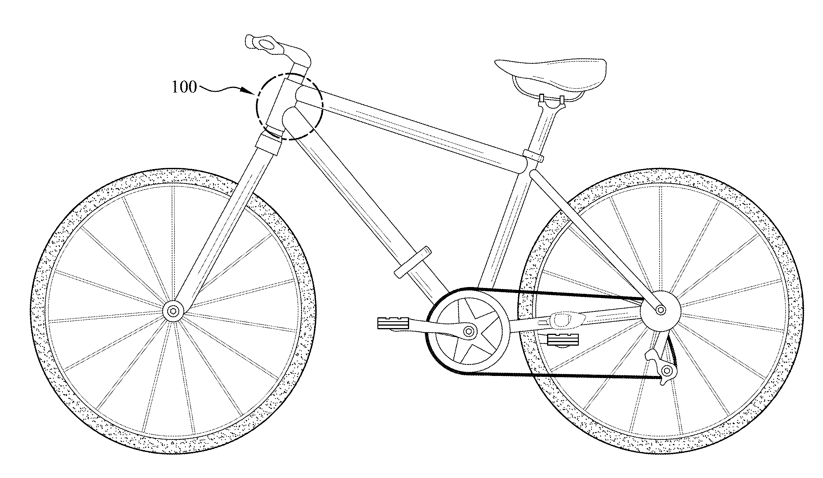
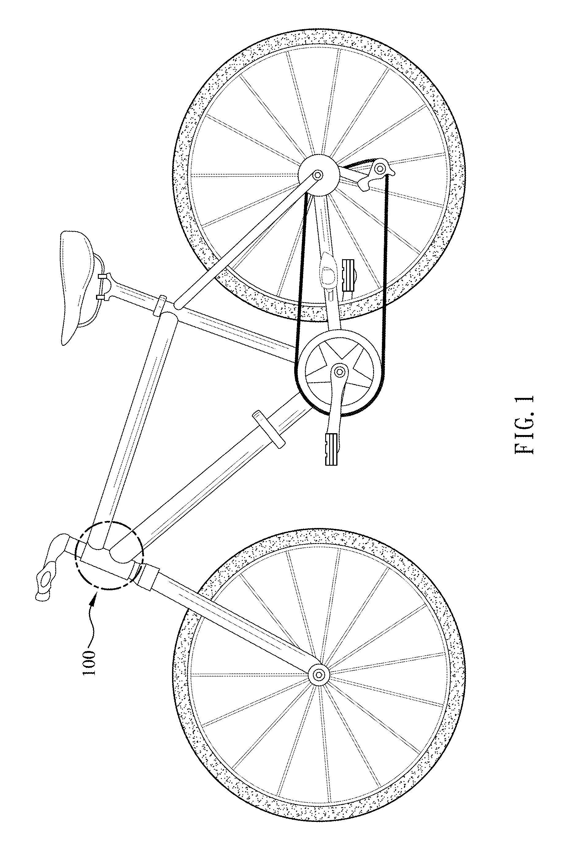
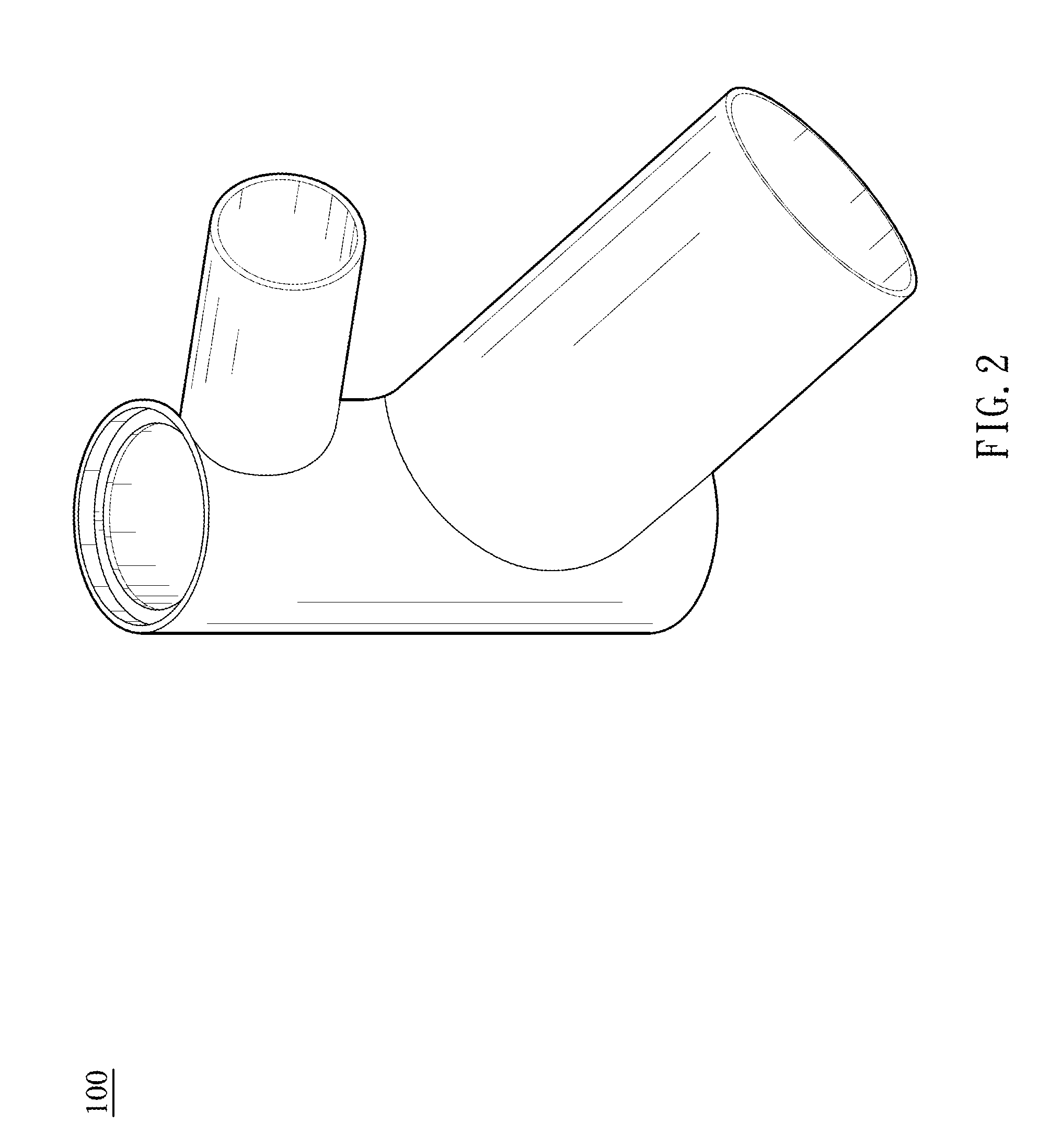
[0023]Referring to FIG. 1 to FIG. 4, the present invention provides a bicycle component 100 with reinforced structure, comprising a main body 10, and a foam material 30.

[0024]The main body 10 is hollow and manufactured by stacking plural carbon fiber prepreg layers 20. Also, the main body 10 is provided with an arc-shaped force bearing area 11. In the embodiment provided by the present invention, the main body 10 is allowed to be a front pipe, a handlebar and a frame.

[0025]The foam material 30, which is solid, is disposed on the force bearing area 11 and wrapped by the carbon fiber prepreg layers 20. Moreover, the foam material 30 is provided with a fi...


PUM

PropertyMeasurementUnit
force bearing areaaaaaaaaaaa
taper shapeaaaaaaaaaa
force bearingaaaaaaaaaa

Abstract

A bicycle component with reinforced structure and a manufacturing method thereof are disclosed. The bicycle component includes a hollow main body and a foam material. The main body is manufactured by stacking plural carbon fiber prepreg layers and provided with a force bearing area. The foam material is disposed on the force bearing area and wrapped by the carbon fiber prepreg layers. Therefore, the present invention improves the structural strength of the bicycle component, lightens the weight of a bicycle made of the bicycle components, and provides a greater controllability of the bicycle.

Description

BACKGROUND OF THE INVENTION[0001]1. Field of the Invention[0002]The present invention relates to bicycle components, and more particularly, to a bicycle component with reinforced structure and a manufacturing method thereof.[0003]2. Description of the Related Art[0004]In order to achieve a lighter weight of a bicycle, most of bicycle-related industries have already used carbon fiber composites to manufacture bicycle components, such as frames, front forks, handlebars, vertical pipes, seat tubes, cranks, and rims, so as to satisfy the demands of consumers.[0005]The force bearing area of each bicycle component mostly locates on a turning or bending section, resulting in stress concentration, thereby causing structure damages and further affecting normal usage. Therefore, to overcome such problems, bicycle-related industries increase the thickness of the force bearing area to improve the structural strength thereof, and also increase the cross-sectional square measure of such area, whe...

Claims


Application Information

Patent Timeline
Patent Type & Authority Applications(United States)
IPC IPC(8): B62K21/04B29C70/46B29C70/68B29C49/02B29C49/00
CPCB62K21/04B29C49/02B29C49/0005B29K2105/04B29C70/467B29C2049/028B29C70/68B62K3/04B62K19/16B62K19/32B29K2105/0872B29K2307/04B29L2031/3091B62K19/28B29C49/0685
Inventor WU, BILL
Owner LIU LOUIS
Learn More