Method of depositing abradable coatings under polymer gels

Active Publication Date: 2016-10-27
GENERAL ELECTRIC CO
View PDF2 Cites 26 Cited by
  • Summary
  • Abstract
  • Description
  • Claims
  • Application Information

AI Technical Summary

Benefits of technology

[0014]According to instant embodiments, a method of depositing abradable coating on a gas turbine engine component is provided. The gas turbine engine component is formed of ceramic matrix composite (CMC) and one or more layers, including at least one environmental barrier coating may be disposed on the outer layer of the CMC. An ou

Problems solved by technology
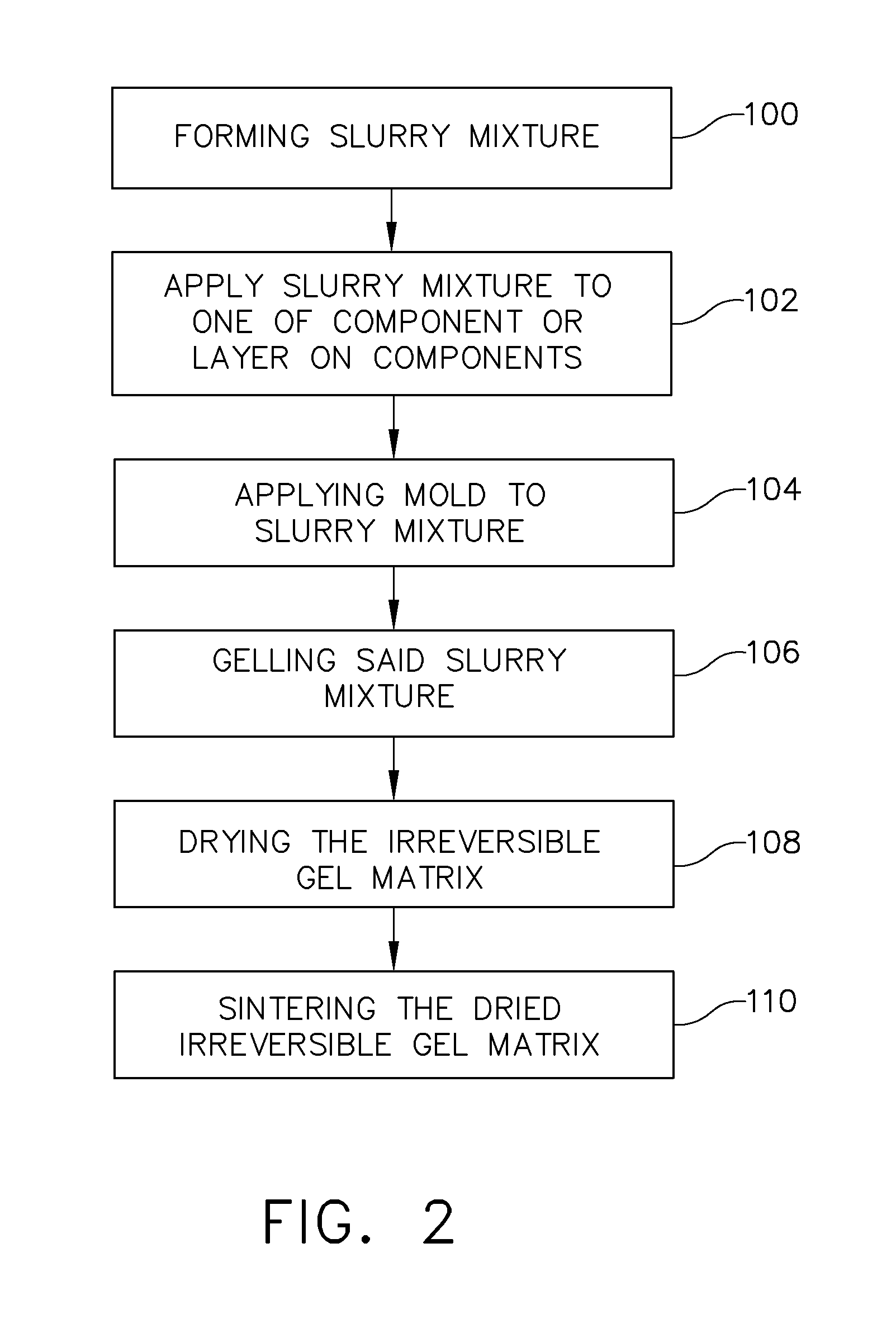
However, as operating temperatures increase, the high temperature durability of the components of the gas turbine engine must correspondingly increase.
This bypass causes loss of efficiency in the gas turbine engine.
During engine operation, the blade tips can rub against the s

Method used


Image

  • Method of depositing abradable coatings under polymer gels
  • Method of depositing abradable coatings under polymer gels
  • Method of depositing abradable coatings under polymer gels

Examples


example 1

Gel-Casting Approach

[0117]Glycerol (low vapor pressure liquid), N-(hydroxymethyl) acrylamide (monomer), polyacrylic acid-polyethylene oxide copolymer (anionic dispersant), yttrium-doped ytterbium disilicate (primary material), Fe3O4 iron oxide (sintering aid), and Al2O3 (sintering aid) were combined in a plastic bottle along with 0.25″ diameter yttrium-doped zirconium dioxide milling media. The mixture was rolled on a roller mill for at least 12 hours.

[0118]A 10 percent (by weight) ammonium persulfate initiator solution was then dosed into the slurry followed by vigorous mixing by hand for several minutes.

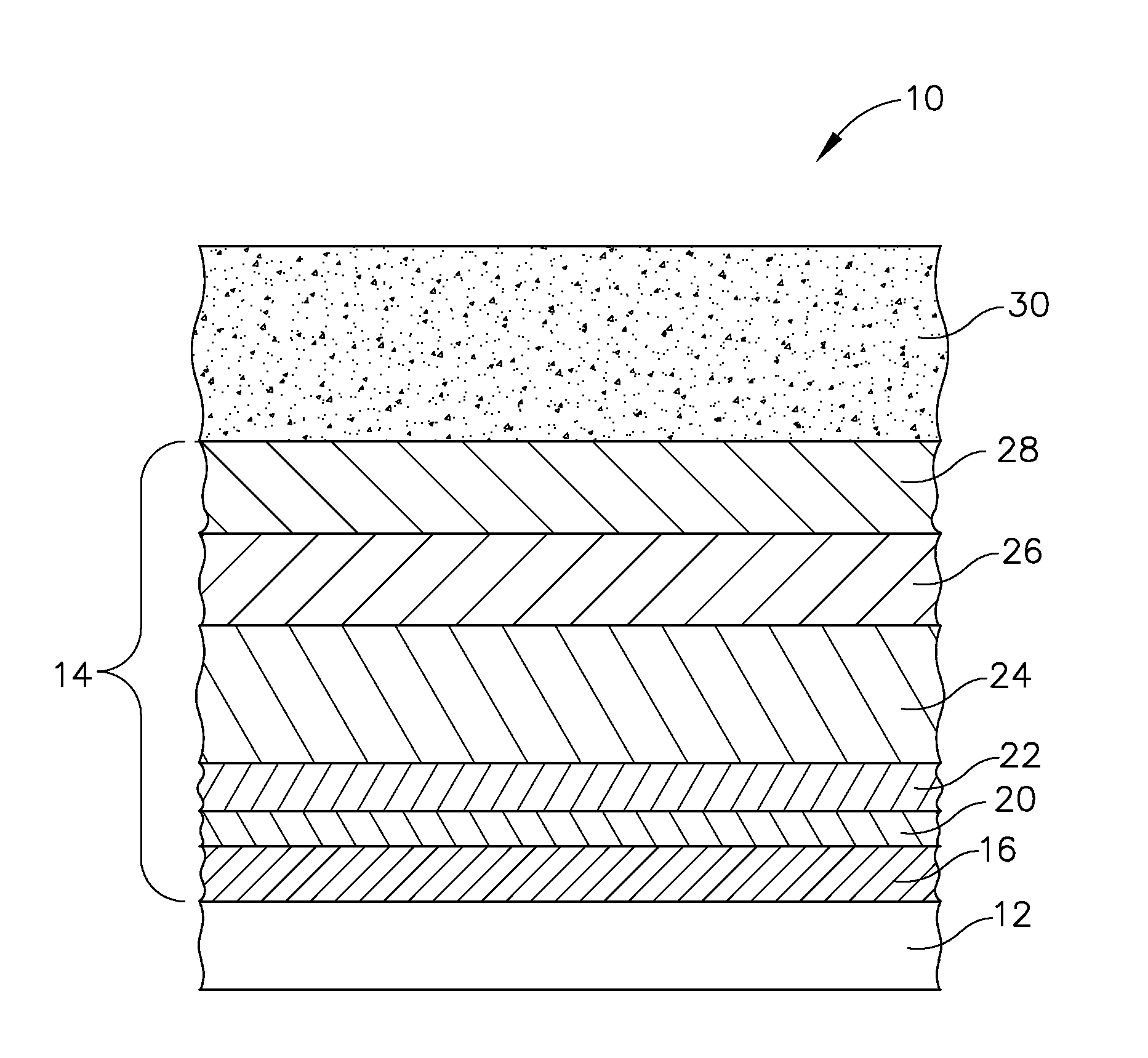
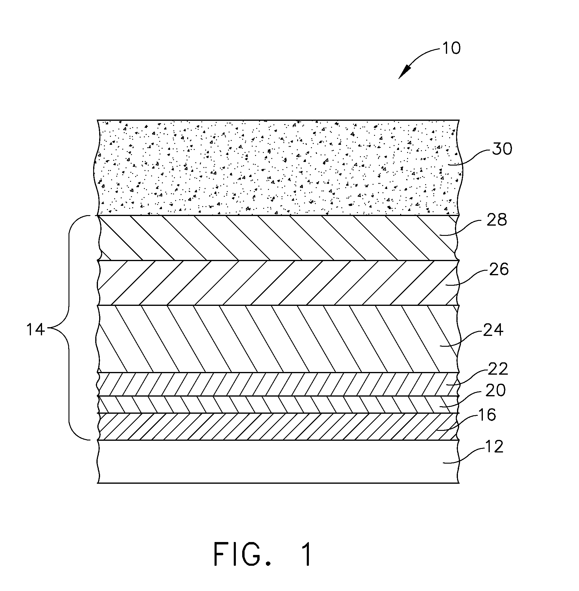
[0119]Next, the slurry was cast on top of a silicon carbide coupon that already had a silicon metal bond coat deposited via a chemical vapor deposition process and a Fe-doped ytterbium disilicate transition layer (hermetic with 5 percent porosity or less) deposited via a slurry deposition process. The slurry was leveled using a doctor blade to remove excess slurry and set the desir...

example 2

Direct-Write Approach

[0125]1-hexanol (high vapor pressure liquid), diethylene glycol monobutyl ether (low vapor pressure liquid), yttrium-doped ytterbium disilicate powder (coarse average particle size primary material), yttrium-doped ytterbium disilicate (fine average particle size primary material), Fe3O4 iron oxide (sintering aid), Al2O3 aluminum oxide (sintering aid), and poly N-vinylpyrrolidone (cationic dispersant, binder) were combined in a plastic bottle along with 0.25″ diameter spherical yttrium doped zirconium oxide media. The mixture was rolled on a roller mill for at least 12 hours. Next, a 50% aqueous solution of polyacrylic acid was added to the slurry, followed by rapid stirring by hand. After about 1 minute of stirring, the slurry became a strongly shear-thinning, reversible gel suitable for direct write deposition.

[0126]Next, the reversible gel “direct-write” slurry was extruded through a syringe on top of a silicon carbide coupon that already had a silicon metal b...


PUM

PropertyMeasurementUnit
Temperatureaaaaaaaaaa

Abstract

A method of depositing abradable coating on an engine component is provided wherein the engine component is formed of ceramic matrix composite (CMC) and one or more layers, including at least one environmental barrier coating, may be disposed on the outer layer of the CMC. An outermost layer of the structure may further comprise a porous abradable layer that is disposed on the environmental barrier coating and provides a breakable structure which inhibits blade damage. The abradable layer may be gel-cast on the component and sintered or may be direct written by extrusion process and subsequently sintered.

Description

CROSS-REFERENCE TO RELATED APPLICATIONS[0001]This application is a national stage application under 35 U.S.C. §371(c) of prior filed, co-pending PCT application serial number PCT / US2014 / 064576, filed on Nov. 7, 2014, which claims priority to U.S. provisional patent application Ser. No. 61 / 915,399, titled “Method of Depositing Abradable Coatings Under Polymer Gels”, filed Dec. 12, 2013. The above-listed applications are herein incorporated by reference.STATEMENT REGARDING FEDERALLY SPONSORED RESEARCH[0002]This invention was made with Government support under Contract No. N00019-04-C-0093 awarded by a Federal Agency. The Government may have certain rights in this invention.TECHNICAL FIELD[0003]The disclosed embodiments generally pertain to shrouds or blades for gas turbine engines. More particularly, but not by way of limitation, present embodiments relate to deposition of abradable coatings on a shroud or blade.BACKGROUND[0004]A typical gas turbine engine generally possesses a forwar...

Claims


Application Information

Patent Timeline
IPC IPC(8): F01D5/28C04B35/624C04B35/622C04B41/00C04B41/50F01D25/08C04B41/87C23C16/22C23C16/56C23C16/44F01D9/02C04B35/515C04B41/52
CPCF01D5/288F05D2260/231C04B35/624C04B35/62222C04B41/0009C04B41/5024C04B41/52C04B41/87C23C16/22C23C16/56C23C16/44F01D9/02F01D25/08C04B2235/3427C04B2235/3272C04B2235/3217F05D2220/32F05D2230/314F05D2300/6033F05D2300/516F05D2240/35C04B35/5156C04B41/009C04B41/89F01D5/284F01D11/12F01D11/122F01D11/125C04B35/806C04B35/565C04B35/584C04B41/4531C04B41/5096C04B41/4539C04B41/4572C04B41/4582C04B41/85C04B41/5025C04B41/5071C04B41/522C04B41/5035Y02T50/60
Inventor KIRBY, GLEN HAROLD
Owner GENERAL ELECTRIC CO
Why Eureka
Try Eureka