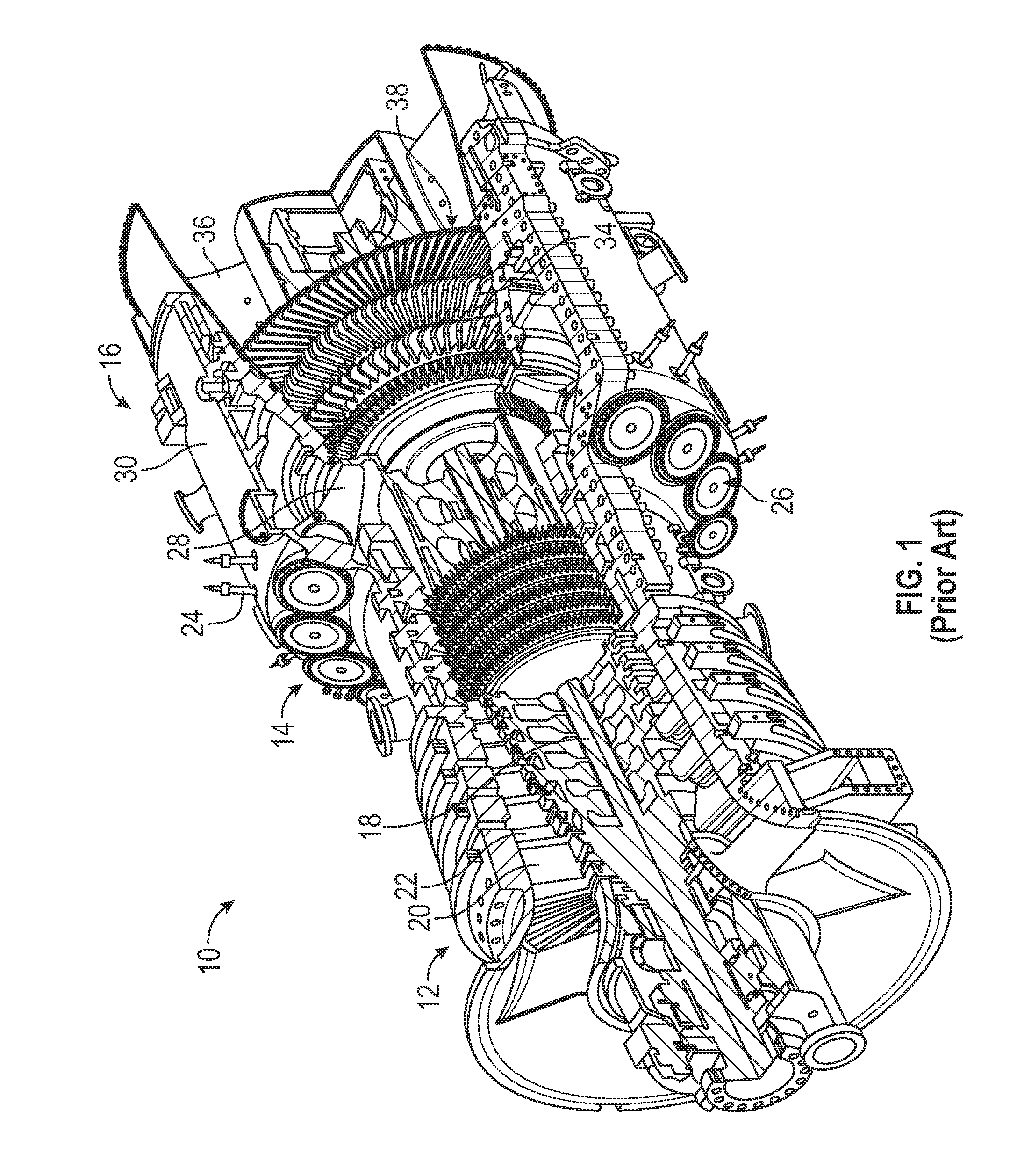
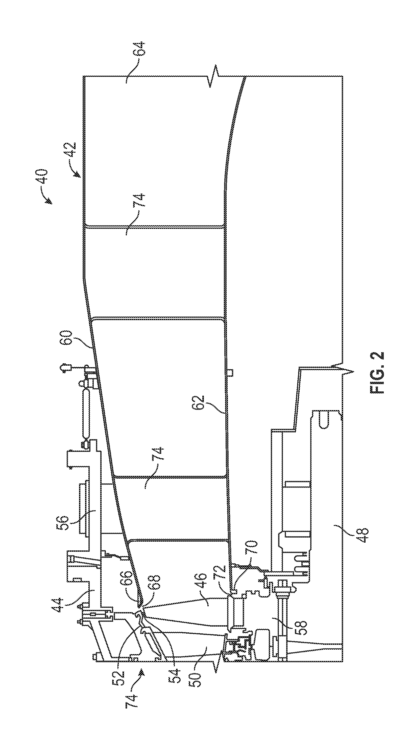
High performance robust gas turbine exhaust with variable (adaptive) exhaust diffuser geometry
a gas turbine engine and exhaust gas diffuser technology, which is applied in the direction of engines, machines/engines, mechanical apparatus, etc., can solve the problems of reducing the tip clearance, increasing the blade length, and affecting the performance so as to achieve the optimal angular orientation of the exhaust gas diffuser for an average ambient temperature and not optimal
- Summary
- Abstract
- Description
- Claims
- Application Information
AI Technical Summary
Benefits of technology
Problems solved by technology
Method used
Image
Examples
second embodiment
[0023]FIG. 3 is a cut-away, isometric view of an exhaust gas diffuser 80 similar to the exhaust gas diffuser 42, where like elements are identified by the same reference number, showing one non-limiting example of the second embodiment referred to above for the actuated diffuser element design. In this embodiment, the end portion 66 is replaced with an actuation ring 82 including a plurality of alternating non-actuated sections 84 and actuated diffuser flap sections 86, where side edges of the actuated diffuser sections 86 lay on top of adjacent side edges of the non-actuated sections 84 to prevent gas leakage therebetween, as shown. Each of the actuated diffuser sections 86 include a hinge 88 and each of the non-actuated sections 84 include a hinge 90 that are mounted to a circular rod 92 circumferentially disposed about an end of the outer liner 60. In one embodiment, pairs of a non-actuated section 84 and an actuated section 86 are coupled together so that when the actuated secti...
first embodiment
[0025]FIG. 4 is a cut-away, cross-sectional type view of an end portion of a gas turbine engine 100 including a turbine section 102 and an exhaust gas diffuser 104, where like elements to the gas turbine engine 40 and the exhaust gas diffuser 80 are identified by the same reference number, showing one non-limiting example of the semi-fixed exhaust gas diffuser for the first embodiment referred to above. The engine 100 includes an exhaust baffle seal 108 and a support link 106 both coupled to the outer liner 60 and the exhaust casing 56, as shown. It is noted that only a single one of the actuated sections 86 is shown with the understanding that there are a number of circumferentially disposed sections 86, where each of the actuated sections 86 will include an associated non-actuated section 84 coupled thereto, and where pairs of the non-actuated sections 84 and the actuated sections 86 are configured around the end portion of the diffuser 104 in the same manner as the diffuser 80. I...
third embodiment
[0027]FIG. 5 is simplified top view of a gas turbine engine 150 including a compressor section 152, a combustion section 154 and a turbine section 156 of the type discussed above. The engine 150 also includes an exhaust gas diffuser 158 extending from the turbine section 156 that is suitable for the pressure-actuated third embodiment referred to above, where the exhaust gas diffuser 158 may include a variation of the non-actuated sections 84 and the actuated sections 86 discussed above. In order to control the position of the sections 86 based on the operating conditions of the engine 150, bleed air from the compressor section 152 is provided on line 162 to the exhaust gas diffuser 158 through a valve 164, where the line 162 is coupled to a bleed orifice 166 at the diffuser 158. The pressure provided at the bleed orifice 166 is scheduled or controlled by an engine control system 168 that controls the valve 164 and the bleed orifice 166. The scheduling relates the engine bleed pressu...
PUM
 Abstract
Description
Claims
Application Information
 - R&D
- Intellectual Property
- Life Sciences
- Materials
- Tech Scout
- Unparalleled Data Quality
- Higher Quality Content
- 60% Fewer Hallucinations
Browse by: Latest US Patents, China's latest patents, Technical Efficacy Thesaurus, Application Domain, Technology Topic, Popular Technical Reports.
© 2025 PatSnap. All rights reserved.Legal|Privacy policy|Modern Slavery Act Transparency Statement|Sitemap|About US| Contact US: help@patsnap.com


