Antenna device

a technology of antenna device and antenna device, which is applied in the direction of resonant antenna, resonant antenna, active element feed, etc., can solve the problems of affecting the external appearance of the vehicle, generating wind noise, damage to the rod antenna device, etc., and enhancing the reception sensitivity to radio waves. , the effect of height reduction

Inactive Publication Date: 2016-10-27
MITSUMI ELECTRIC CO LTD
View PDF7 Cites 37 Cited by
  • Summary
  • Abstract
  • Description
  • Claims
  • Application Information

AI Technical Summary

Benefits of technology

[0011]The present invention has been made in view the above circumstance, and an object of the present invention is to provide an antenna device having a height which is less than or equal to a predetermined height (a reduced height) and enhanced receiving sensitivity to radio waves.

Problems solved by technology

Unfortunately, the rod antenna (or helical antenna) device inevitably projects from a vehicle after being mounted thereto, which projection may impair the external appearance of the vehicle.
Furthermore, the rod antenna device may be damaged by the collision with any obstacle, such as the roof of a garage, during the parking operation of the vehicle.
The rod antenna device having an elongated length may generate a wind noise during the driving of the vehicle.
This may bring an unpleasant feeling to the driver and passenger.
Additionally, the rod antenna device is relatively easy to detach and is thus high-theft.
A vehicle antenna device having a greater height from a mounting surface can have a higher receiving sensitivity to radio waves; however, the height of the vehicle antenna device is limited by a design constraint.

Method used


Image

  • Antenna device
  • Antenna device
  • Antenna device

Examples


Embodiment Construction

[0033]Embodiments of the present invention will now be described in detail with reference to the attached drawings. The examples shown in the drawings should not be construed to limit the present invention.

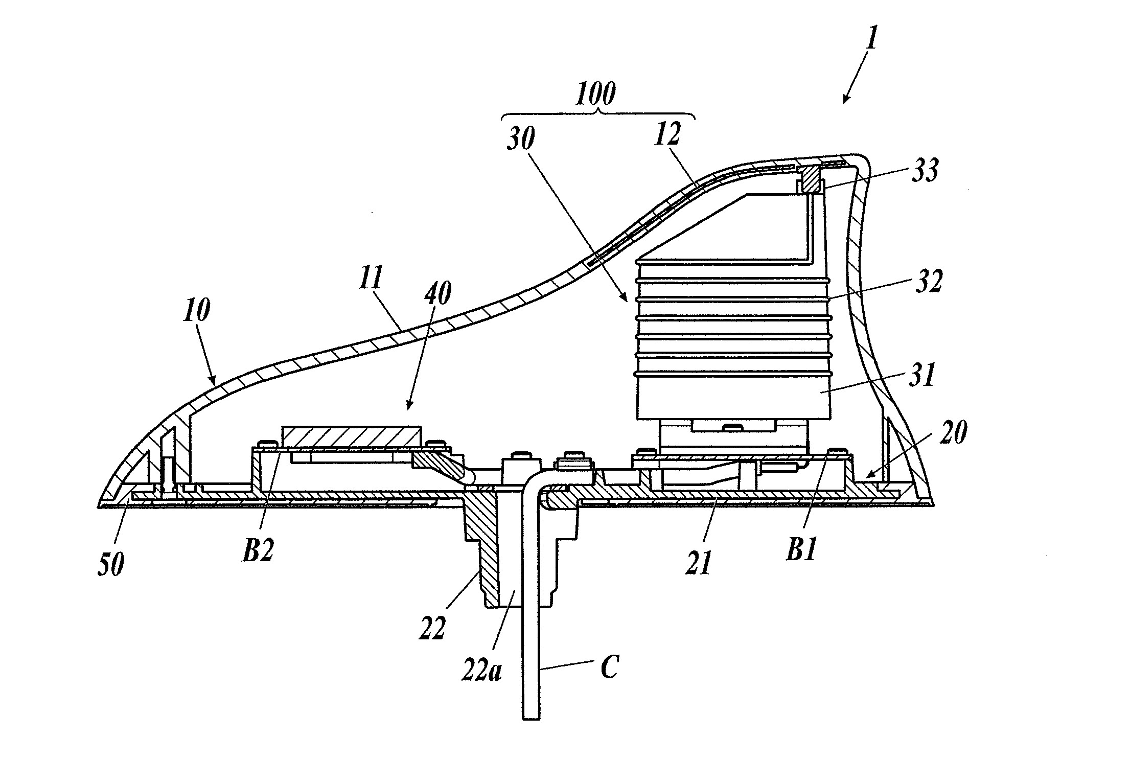
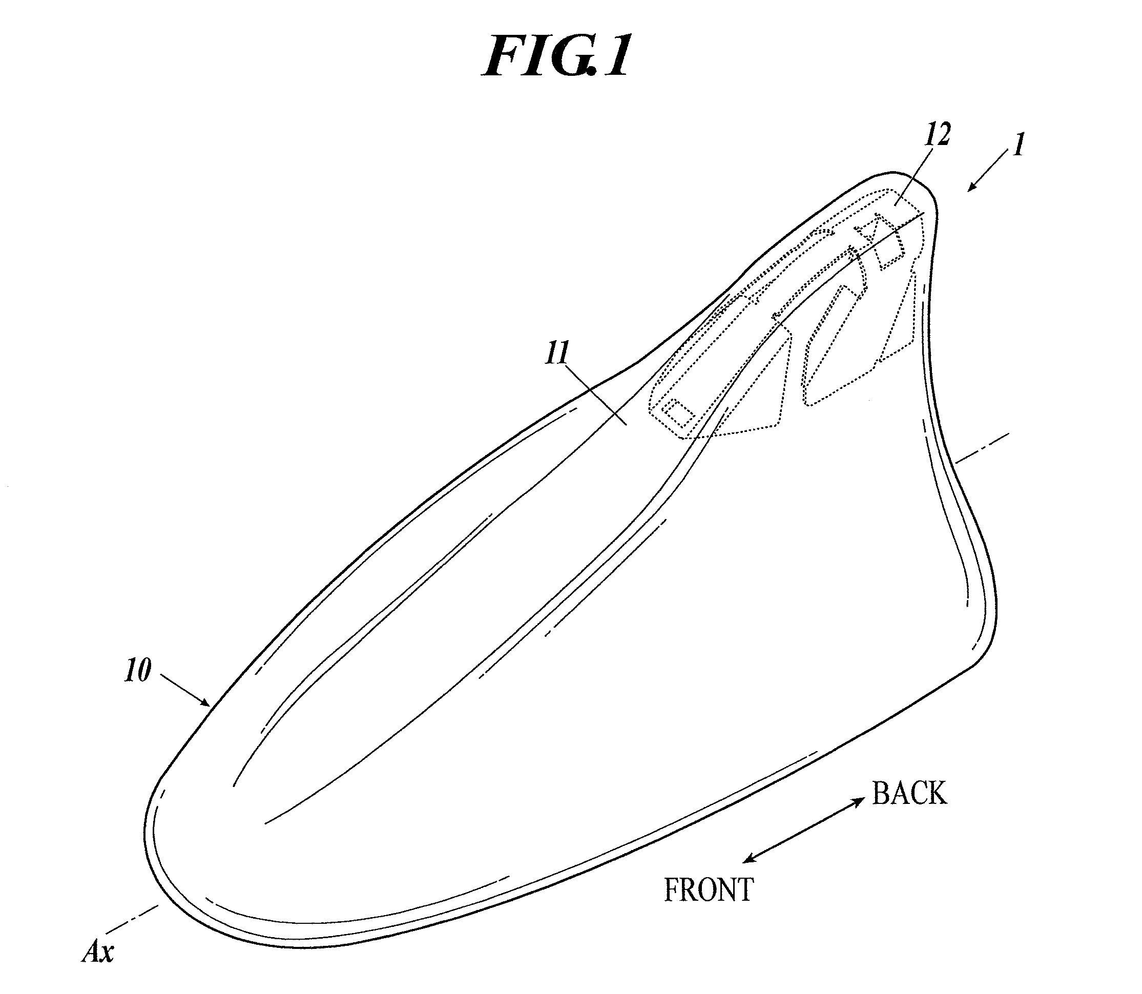
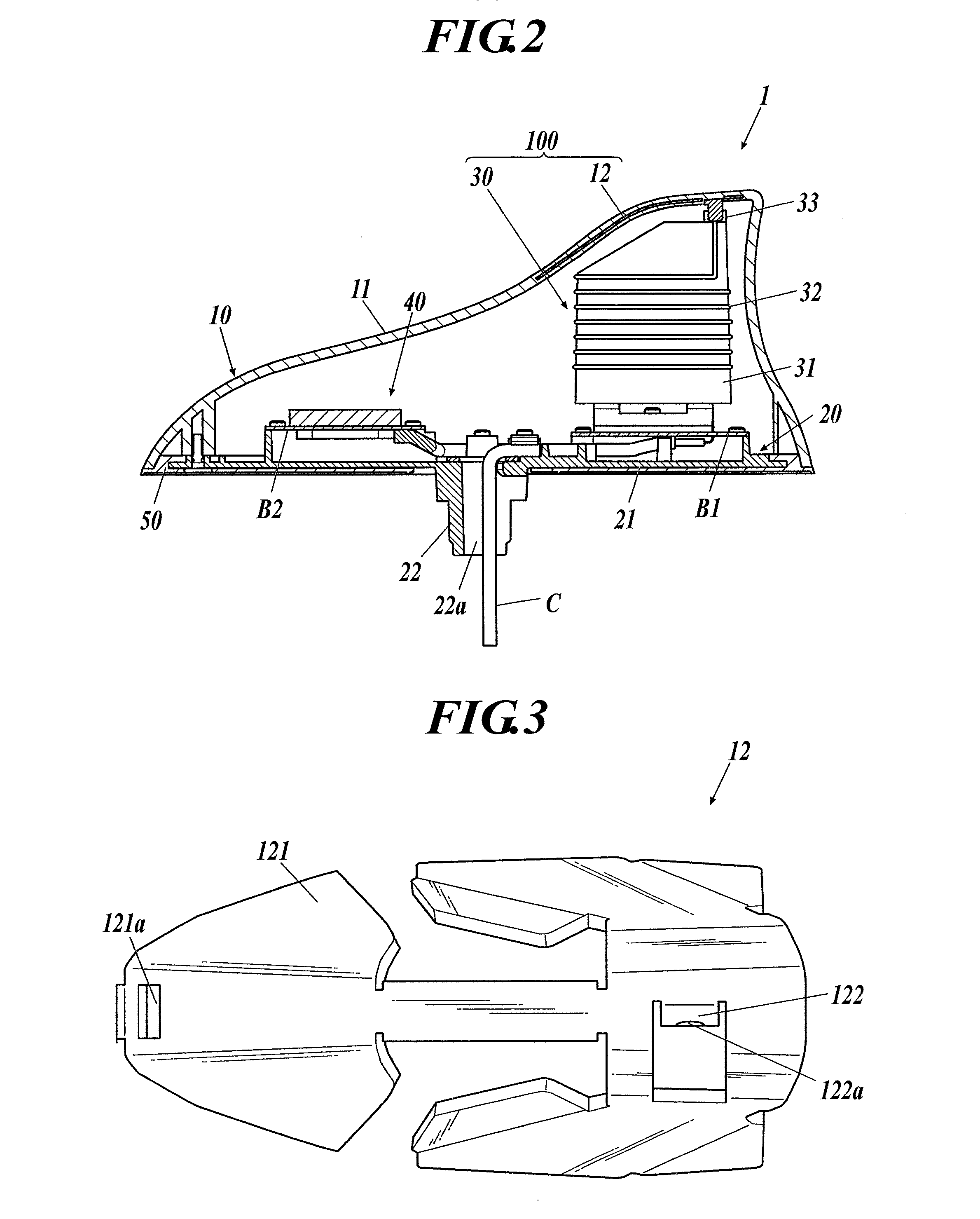
[0034]FIG. 1 is an external view of an antenna device 1 according to an embodiment of the present invention. FIG. 2 is a cross-sectional view of the internal structure of the antenna device 1. The antenna device 1 of the present invention is of a composite type which can receive radio waves having several frequency bands for a GPS and AM and FM broadcasting. The antenna device 1 is a vehicle antenna device to be fixed on a mounting surface, such as the roof of a vehicle.

[0035]With reference to FIGS. 1 and 2, the antenna device 1 includes an antenna cover 10, an antenna base 20, antenna boards B1 and B2, first and second antenna bodies 30 and 40, and a gasket 50. The first antenna body 30 is part of an antenna assembly to receive radio waves from AM and FM broadcasting stations. Th...


PUM


Abstract

Provided is an antenna device having a reduced height and enhanced receiving sensitivity. The antenna device includes an antenna base and an antenna cover fixed to the antenna base. The antenna cover includes a resin cover body and a capacitive element integrally molded with the cover body and functioning as at least any one of a capacitance hat and an inductor. The antenna device 1 further includes a helical element electrically connected to the capacitive element and an antenna board electrically connected to the helical element and disposed on the antenna base.

Description

BACKGROUND OF THE INVENTION[0001]1. Field of the Invention[0002]The present invention relates to an antenna device.[0003]2. Description of the Related Art[0004]Among vehicle antenna devices, telescopic rod antenna devices (hereinafter referred to as “rod antenna devices”) are generally used to receive amplitude-modulated (AM) and frequency-modulated (FM) broadcasting waves. Such a rod antenna device includes an antenna element (rod) having a length of approximately ¼ the wavelength λ of the FM waves (for example, 1.5 m for a resonant frequency of 50 MHz).[0005]In such a rod antenna device, an antenna element adapted to the FM frequency band is used to receive AM waves. The antenna element has a resonant frequency mismatched to the AM frequency band and thus includes a resonant circuit and an amplifying circuit to ensure the sensitivity to AM waves. Another type of antenna device is known which includes an insulating rod with an antenna element (lead) spirally wound therearound (here...

Claims


Application Information

Patent Timeline
Patent Type & Authority Applications(United States)
IPC IPC(8): H01Q1/32H01Q1/12H01Q1/40H01Q1/36
CPCH01Q1/3275H01Q1/40H01Q1/1214H01Q1/362H01Q1/42H01Q1/36H01Q9/36
Inventor KIRIYAMA, HIROYUKIMIURA, RYUTARO
Owner MITSUMI ELECTRIC CO LTD
Why Eureka
Try Eureka