
Method and apparatus for producing a tube of glass

Active Publication Date: 2016-11-03
HERAEUS QUARZGLAS
View PDF31 Cites 2 Cited by
  • Summary
  • Abstract
  • Description
  • Claims
  • Application Information

AI Technical Summary

Benefits of technology

The present invention provides a method to make a high-quality glass tube with a large outer diameter and high dimensional accuracy in a single or few forming steps. This method allows for a diameter change of 40 mm or more in a single forming stage, which makes it possible to produce large tubes of quartz glass with acceptable energy expenditure and without pronounced drawing streaks and tolerable siding.

Problems solved by technology

The larger the tube end diameter, the more difficult and expensive becomes the production of a dimensionally accurate large tube.
On the other hand, it is evident that this procedure is very time- and energy-consuming, especially since the tube cools down between successive forming steps.
However, it has been found that dimensional deviations already existing in the original hollow cylinder tend to continue into the drawn-off glass tube in the forming process and are even intensified.
Variations in the radial cross-sectional profile or wall one-sidedness, i.e. radially irregular course of the tube wall thickness, which is also called “siding” among the experts, are particularly disadvantageously noticeable.
With increasing tube end diameter, these problems increase.
The greater the blow pressure, the more the thickness difference will be noticed, so that the blow pressure cannot be arbitrarily high.
This, however, results in pronounced drawing streaks and other defects in the glass wall and in an increased energy demand, especially in the case of large-volume tubes (hereinafter also called “large tubes”), which on account of their large size cool down particularly rapidly.

Method used


Image

  • Method and apparatus for producing a tube of glass
  • Method and apparatus for producing a tube of glass
  • Method and apparatus for producing a tube of glass

Examples


Embodiment Construction

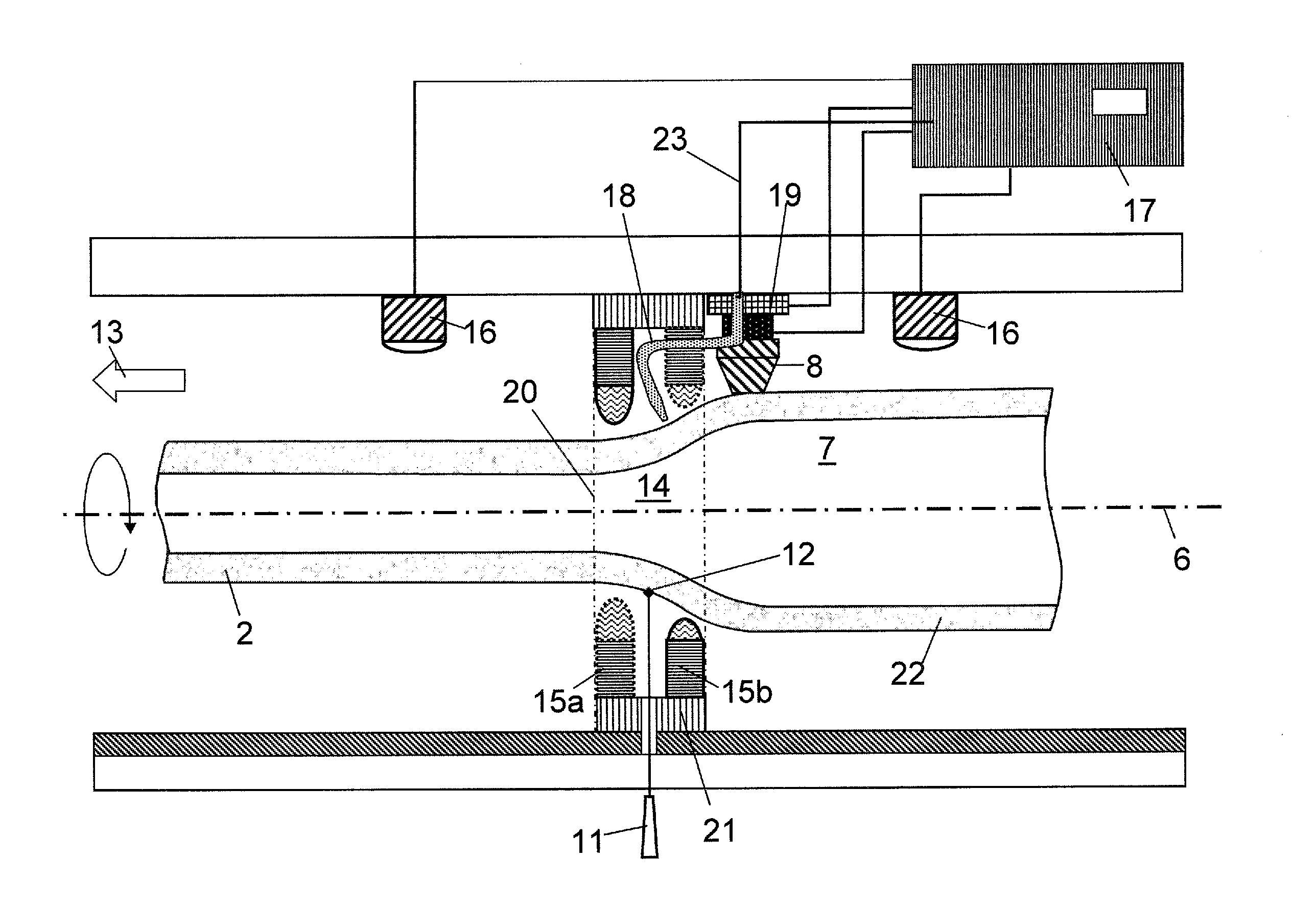
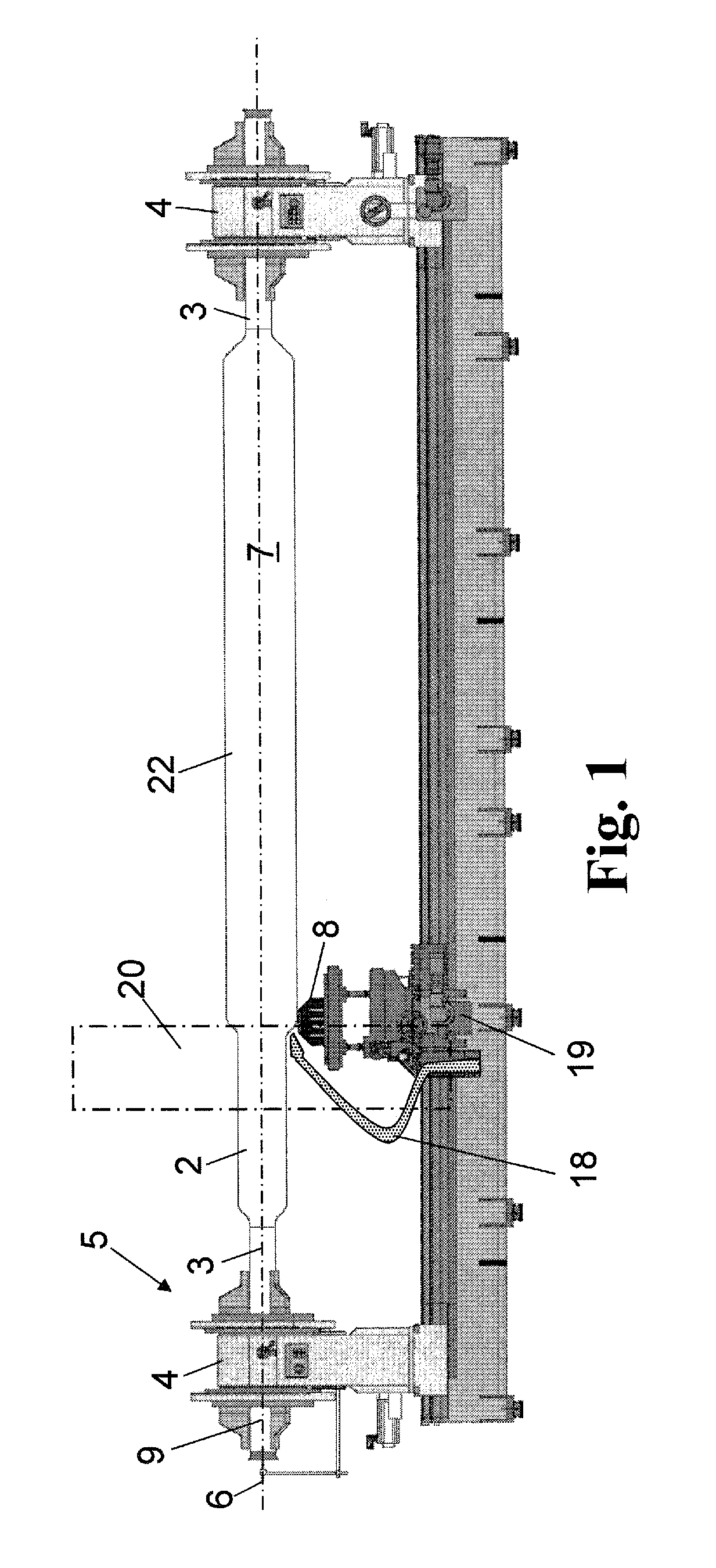
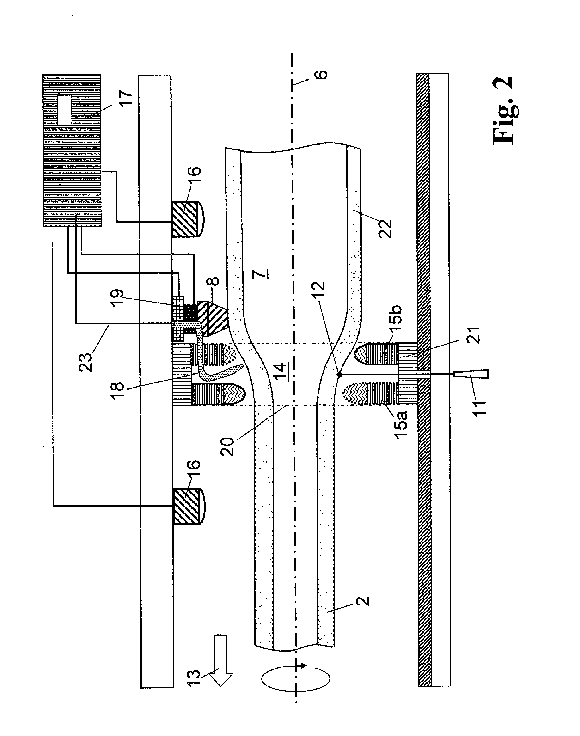
[0067]FIG. 1 schematically shows an apparatus for forming a hollow cylinder 2 of quartz glass into a larger tube 22. The forming process comprises several forming stages in which the respective initial hollow cylinder is formed, starting from an outer diameter of 300 mm, successively into the desired larger tube 22 having an outer diameter of 960 mm and a wall thickness of 7.5 mm.

[0068]Holding tubes 3 are welded onto the ends of the hollow cylinder 2 of quartz glass which is to be formed. The holding tubes 3 are clamped in chucks 4 of a horizontal glass lathe 5, which are synchronously rotating about the rotation axis 6. A burner carriage 21 (see FIG. 2), on which a plurality of burners are distributed in ring form around the outer circumference of the hollow cylinder 2, is moved from one hollow-cylinder end to the other end, thereby heating the hollow cylinder 2 of quartz glass zone by zone and around its entire circumference. The burner carriage 21 is symbolized in FIG. 1 by a das...


PUM

PropertyMeasurementUnit
Pressureaaaaaaaaaa
Pressureaaaaaaaaaa
Diameteraaaaaaaaaa

Abstract

A method and apparatus are provided for producing a tube of glass by zonewise heating and softening of a hollow cylinder by a movable heating zone while rotating about its rotation axis. The glass tube is continuously formed by radial expansion of the softened region under action of centrifugal force and / or internal overpressure applied in the hollow-cylinder bore. The method and apparatus make it possible to deform the hollow cylinder in a single or a small number of forming steps into a glass tube having a larger outer diameter and high dimensional accuracy by determining a circumferential position at which the wall thickness is comparatively small, and during heating and softening of the rotating hollow cylinder a coolant is dispensed from a coolant source onto the deformation zone only when or predominantly when the circumferential position having the comparatively small wall thickness passes the coolant source.

Description

BACKGROUND OF THE INVENTION[0001]1. Technical Field[0002]The present invention relates to a method for producing a tube of glass, particularly of quartz glass, comprising the following method steps:[0003](a) providing a hollow cylinder of the glass having a wall thickness and having an outer diameter D1,[0004](b) zonewise heating and softening the hollow cylinder which is rotating about a rotation axis in a heating zone moved relative to the rotation axis,[0005](c) forming a deformation zone by radial expansion of the softened area under the action of a centrifugal force and / or an internal overpressure applied in the hollow cylinder bore, and[0006](d) continuously forming the tube to produce an outer diameter D2 which is greater than D1.[0007]Moreover, the present invention relates to an apparatus for performing such a method, comprising:[0008]a rotation device for rotating a hollow cylinder of glass about its longitudinal axis, which cylinder has an inner diameter, an outer diamete...

Claims


Application Information

Patent Timeline
IPC IPC(8): C03B23/08C03B23/07C03B23/043C03B23/053
CPCC03B23/08C03B23/043C03B23/07C03B23/053C03B23/045C03B20/00C03B27/028
Inventor GROMANN, BORISSOHN, MATTHIASBLUMENAU, ALEXANDER
Owner HERAEUS QUARZGLAS
Learn More