Method and apparatus for encapsulating a light source

a technology of light source and encapsulation device, which is applied in the direction of lighting and heating apparatus, instruments, fibre light guides, etc., can solve the problems of limited pavers, difficult to provide adequate structural support, and difficulty in making electronic devices that are protected from water ingress

Active Publication Date: 2016-11-03
DANIELS JOHN JAMES
View PDF14 Cites 17 Cited by
  • Summary
  • Abstract
  • Description
  • Claims
  • Application Information

AI Technical Summary

Benefits of technology

[0007]In accordance with an aspect of the invention, a method provides a strong, durable, waterproof illuminated paver that includes an array of individually addressable light sources, having the aesthetic appearance of a conventional stone material. The method comprises providing a light guide having a light receiving end and a light transmissive end. A light source is provided having a selective on state and a selective off state. The light source is optically coupled to the light receiving end of the light guide to form a light engine comprising the light source and the light guide. The optically coupled light guide and light source are encased within an encapsulating bulk, wherein the encapsulating bulk includes at least one viewable surface, and where the light transmissive end of the light guide is viewable at said at least one viewable surface. An obscuring layer is formed on one or more of the at least one viewable surface for obscuring the transmissive end of the light guide from view when the light source is in the selective off state.
[0008]In accordance with another aspect of the invention, an apparatus comprises a strong, durable, waterproof illuminated paver that includes an array of individually addressable light sources, having the aesthetic appearance of a conventional stone material. The apparatus includes a light guide having a light receiving end and a light transmissive end. A light source has a selective on state and a selective off state, wherein the light source is optically coupled to the light receiving end of the light guide to form a light engine comprising the light source and the light guide. An encapsulating bulk encases the optically coupled light guide and light source therewithin. The encapsulating bulk includes at least one viewable surface. The light transmissive end of the light guide is viewable at said at least one viewable surface. An obscuring layer is provided for obscuring the transmissive end of the light guide from view when the light source is in the selective off state.
[0009]In accordance with another aspect of the invention, a solar paver comprises a light guide having a light receiving end and a light transmissive end. A light to energy device is provided, wherein the light to energy device is optically coupled to the light transmissive end of the light guide to form a solar cell comprising the light to energy device and the light guide. An encapsulating bulk encases the optically coupled light guide and light to energy device therewithin. The encapsulating bulk includes at least one light receiving surface. The light receiving end of the light guide is at least one light receiving surface. The light to energy device comprises one or more solar die and the light guide comprises one or more individual lenses having each individual lens associated with a respective solar die and LED.

Problems solved by technology

It is difficult to make an electronic device that is protected from water ingress, and often times a low voltage power source, such as 12 volts DC is used to reduce the potential for a shock hazard.
It is also difficult to provide adequate structural support, in particular if the paver includes a cavity having an air gap.
However, in this case, the paver is limited in size.
The single light source of a conventional paver is limited in its ability to convey a message or provide enhanced entertainment and lighting features.
However, such conventional detectable warning surfaces provide no lighting, and also no way to convey messages, such as scrolling sign messages indicating ingress and egress direction, warning, timing (for example, for the next available train), and other information, entertainment or safety lighted indications.

Method used


Image

  • Method and apparatus for encapsulating a light source
  • Method and apparatus for encapsulating a light source
  • Method and apparatus for encapsulating a light source

Examples


Embodiment Construction

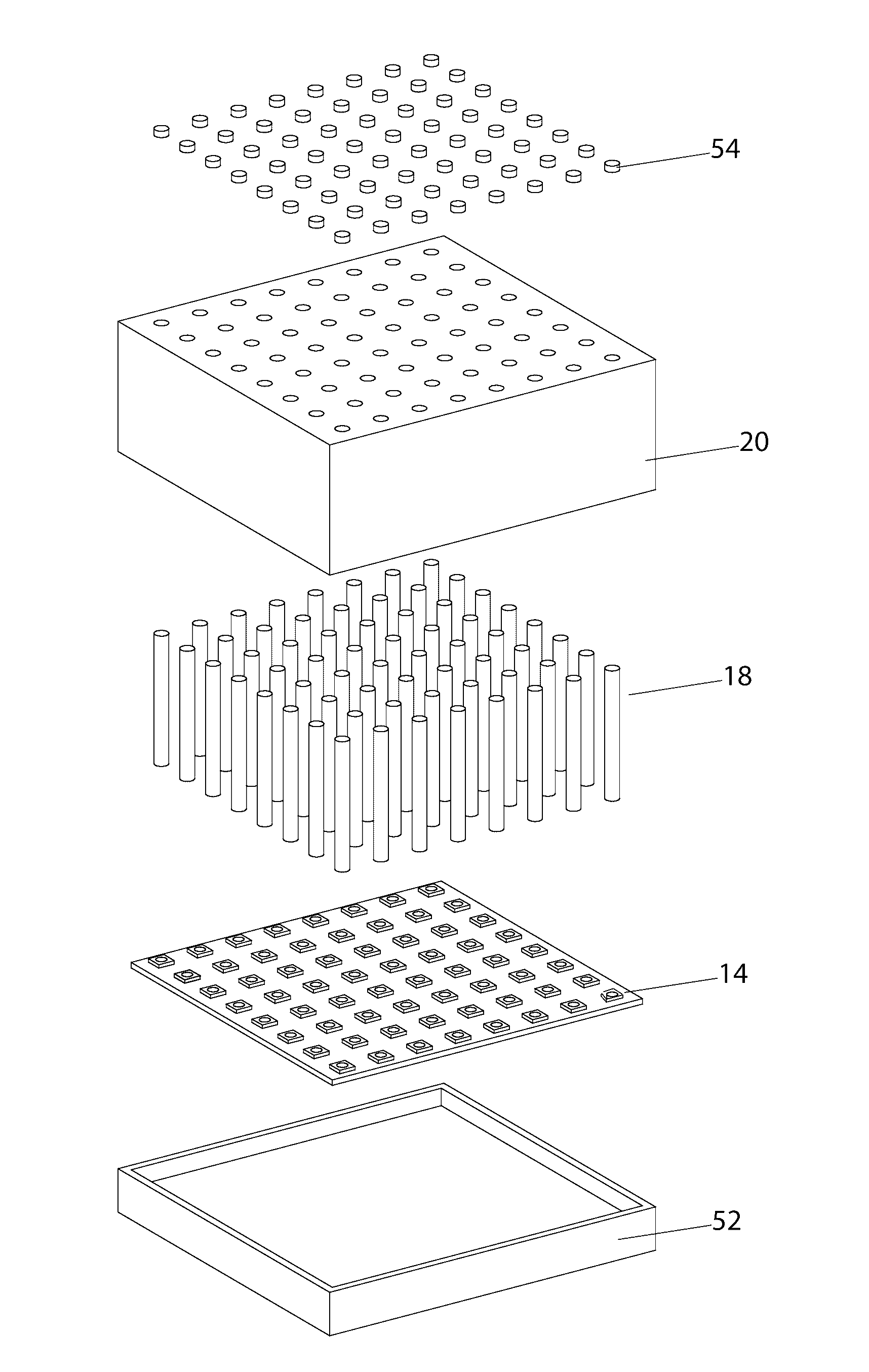
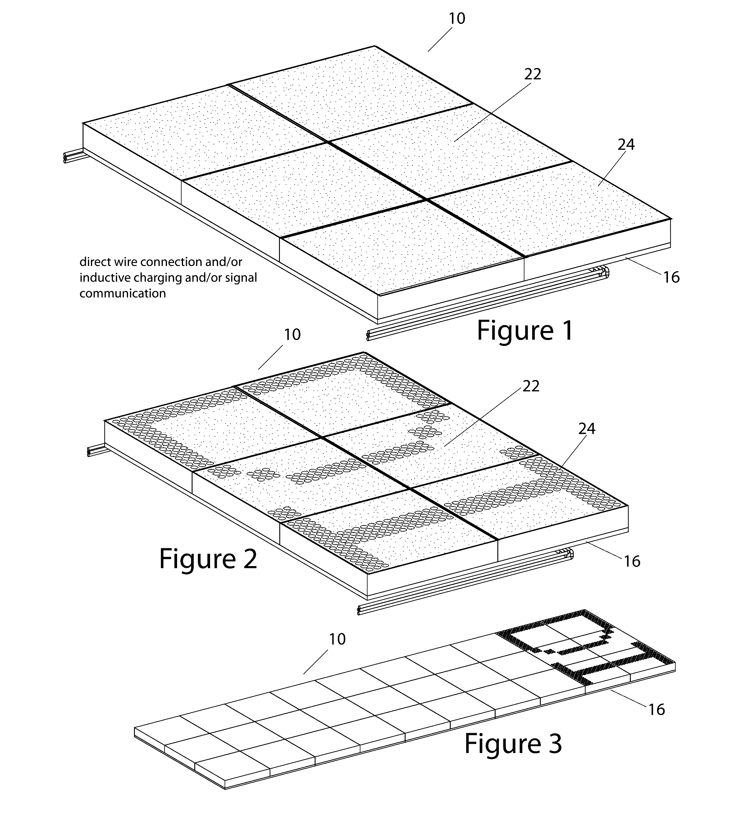
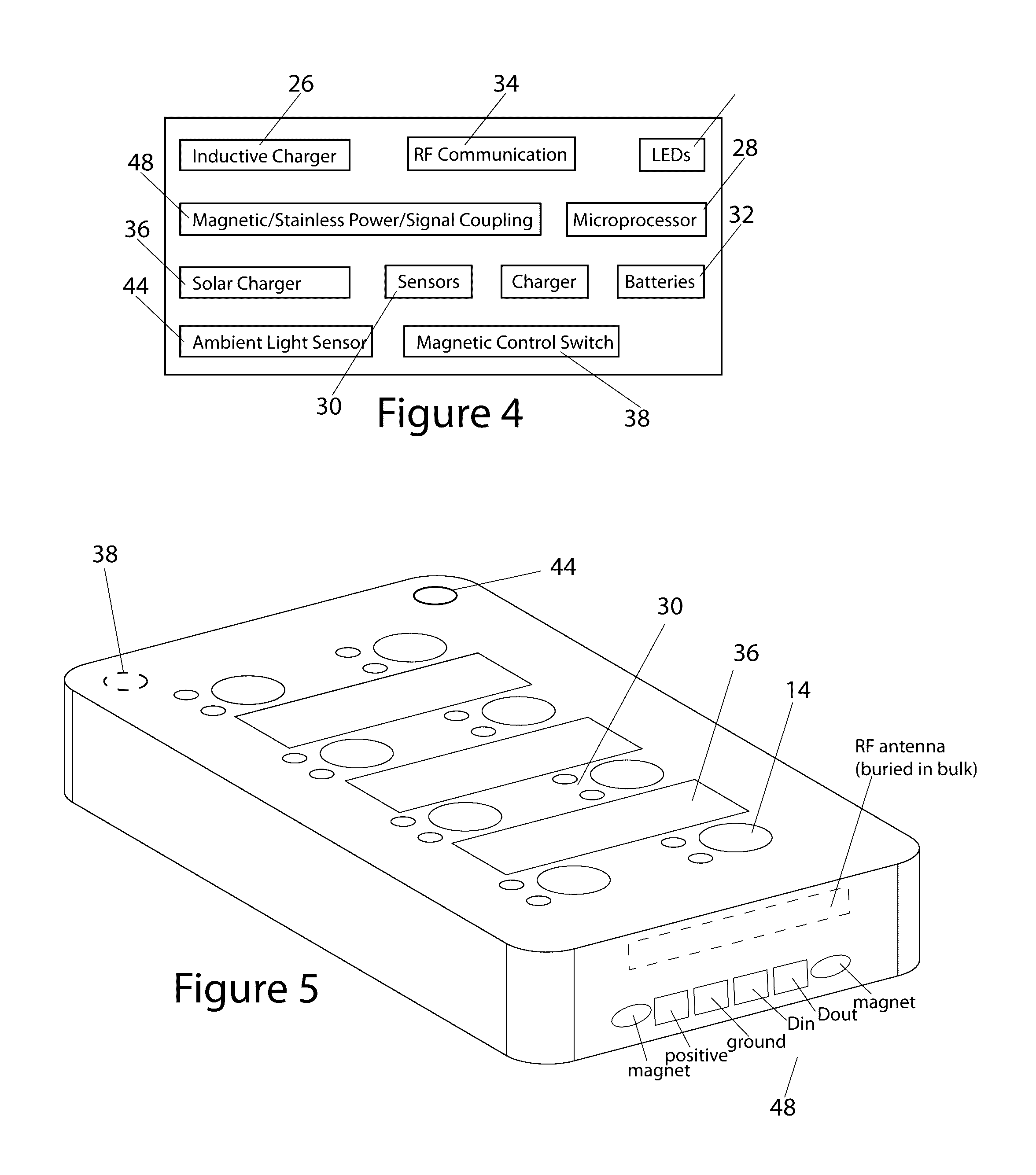
[0091]FIG. 1 shows a section of an assembled pathway 12 constructed using the inventive waterproof, encapsulated lighting sources 10. FIG. 2 shows the section of the assembled pathway 12 constructed using the inventive waterproof, encapsulated lighting sources 10, showing a scrolling message being displayed on individually addressable light sources 14 of a three by two grid of the inventive waterproof, encapsulated lighting sources 10. FIG. 3 shows a larger section of the assembled pathway 12 show in FIG. 2, showing the inventive waterproof, encapsulated lighting sources 10 mounted on an installation-facilitating backer board 16. In accordance with an aspect of the invention, an apparatus comprises a light guide 18 having a light receiving end and a light transmissive end. A light source 14 has a selective on state and a selective off state, wherein the light source 14 is optically coupled to the light receiving end of the light guide 18 to form a light engine comprising the light s...


PUM


Abstract

An apparatus and method for encapsulating a light source within a water-tight, robust encapsulating bulk for use, among other things, as a walk paver. The apparatus and method provides a strong, durable, waterproof illuminated paver that includes an array of individually addressable light sources, having the aesthetic appearance of a conventional stone material. A light guide is provided having a light receiving end and a light transmissive end. A light source is provided having a selective on state and a selective off state. The light source is optically coupled to the light receiving end of the light guide to form a light engine comprising the light source and the light guide. The optically coupled light guide and light source are encased within an encapsulating bulk, wherein the encapsulating bulk includes at least one viewable surface, and where the light transmissive end of the light guide is viewable at said at least one viewable surface. An obscuring layer is formed on one or more of the at least one viewable surface for obscuring the transmissive end of the light guide from view when the light source is in the selective off state.

Description

CROSS REFERENCE TO RELATED APPLICATIONS[0001]This Application is a U.S. Utility Application of Provisional Patent Application 62 / 084,544, filed Nov. 25, 2014 entitled “A Method and Apparatus for Encapsulating a Light Source”, which is incorporated by reference herein.BACKGROUND[0002]The present invention relates to an apparatus and method for encapsulating a light source within a water-tight, robust encapsulating bulk for use, among other things, as a walk paver, wall material, message board, entertainment system, lighting device, pathway lighting, display system, driveway lighting, roadway lighting and the like.[0003]There are many examples of conventional paving stones, commonly referred to as “pavers” used to make driveways, walkways and patios. A typical paver is a solid block of natural stone, or a cast stone-like material such as concrete or so-called “cultured stone”.[0004]Recently, pavers have been provided that include cavities that are used to house light sources, such as ...

Claims


Application Information

Patent Timeline
Patent Type & Authority Applications(United States)
IPC IPC(8): F21V31/00H05K7/20A63J25/00F21V8/00F21V29/89
CPCF21V31/005G02B6/0006F21V29/89F21Y2115/10A63J25/00H05K7/20963G02B6/0008A63G31/00F21S2/00F21V31/00F21V33/006G09F19/22G09F19/228G09F2019/223
Inventor DANIELS, JOHN JAMES
Owner DANIELS JOHN JAMES
Why Eureka
Try Eureka