
Defrost chamber within freezer compartment

a freezer compartment and glass technology, applied in the field of freezer compartment defrosting, can solve the problems of foodborne, increased user attention for submerged items in water, inconvenience for individuals, etc., and achieve the effect of improving or overcoming deficiencies in the ar

Inactive Publication Date: 2016-11-03
WHIRLPOOL CORP
View PDF6 Cites 18 Cited by
  • Summary
  • Abstract
  • Description
  • Claims
  • Application Information

AI Technical Summary

Benefits of technology

The present invention provides a refrigerator with a defrost chamber that can be remotely activated. This may be through a control panel or through wireless connection (like a smartphone). The defrost chamber is designed to be easily removed for storing, retrieving, or cleaning. The front of the defrost chamber is either transparent or translucent to allow for easy identification of the contents. This makes it convenient for users to activate the defrost remotely and at different locations. The technical effect of the invention is to improve the user experience and convenience.

Problems solved by technology

The small temperature differential above freezing generally results in the process taking several hours to thoroughly defrost a food item, resulting in inconvenience for the individual.
However, leaving a food item on a countertop over a period of several hours may be unsafe and result in food borne illness.
However, submerging the item in water requires increased user attention.
In particular, as the food item defrosts and thaws, the water bath conversely heats up, incrementally decreasing the relative temperature differential.
Further, running hot water over the food item may cause the outer layer of the food to heat up to a temperature where harmful bacteria begins to multiply.
The pool is heated significantly faster than the food item, which may result in the outer layer of the food item being prematurely cooked.
Second, the approach also requires increased user attention.
Third, the approach requires the thawed food to be cooked immediately thereafter.

Method used


Image

  • Defrost chamber within freezer compartment
  • Defrost chamber within freezer compartment
  • Defrost chamber within freezer compartment

Examples


Embodiment Construction

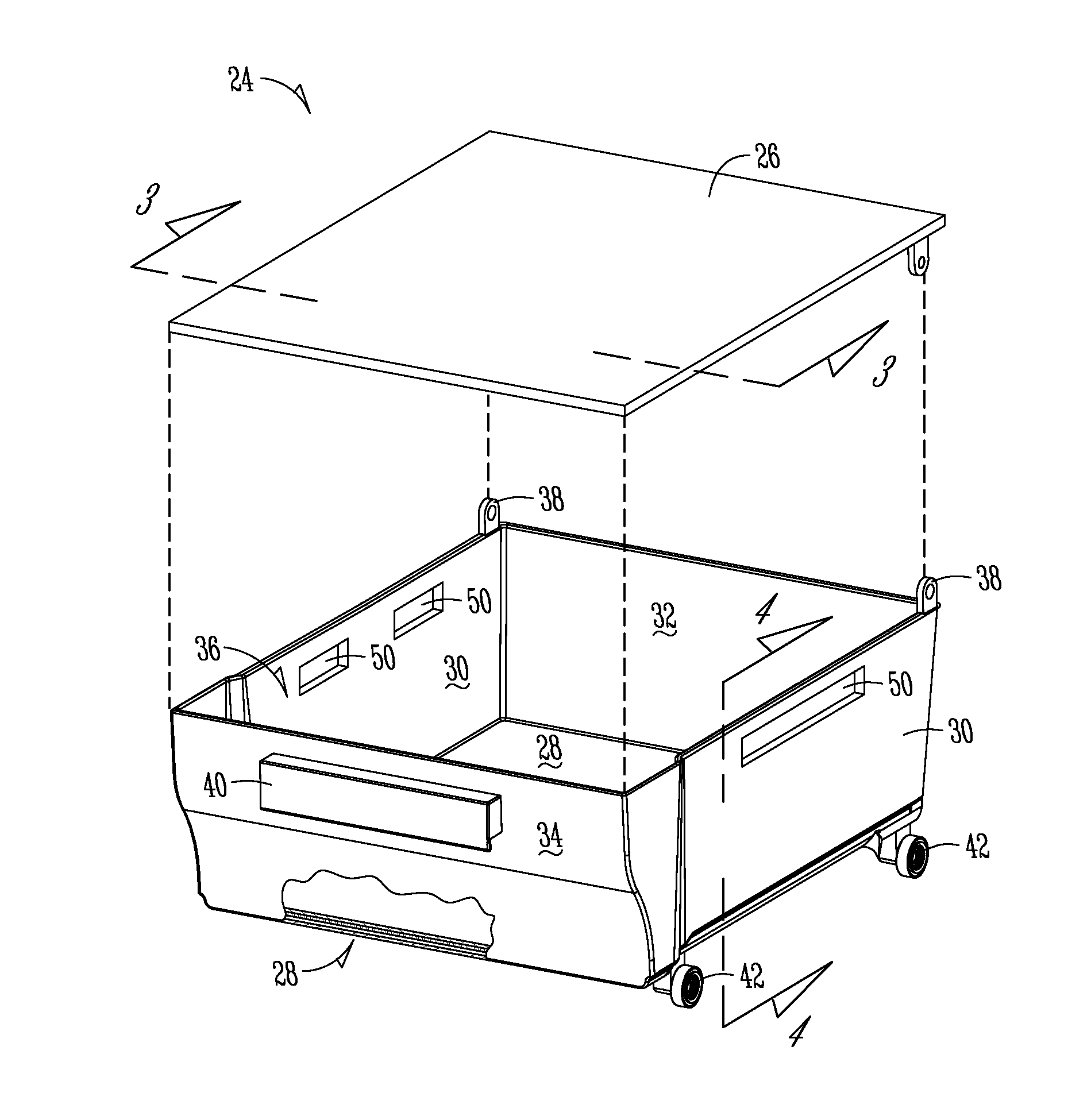
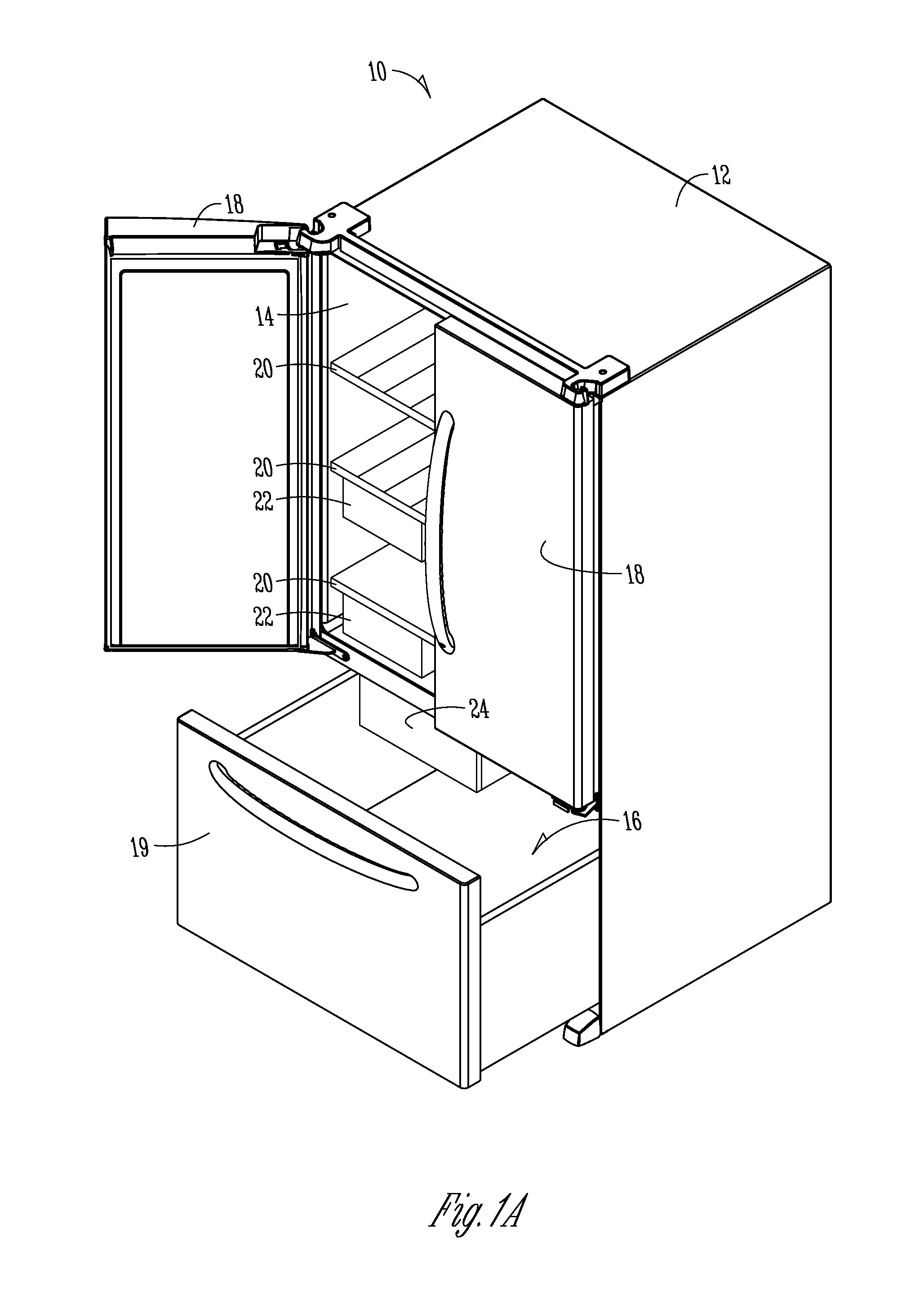
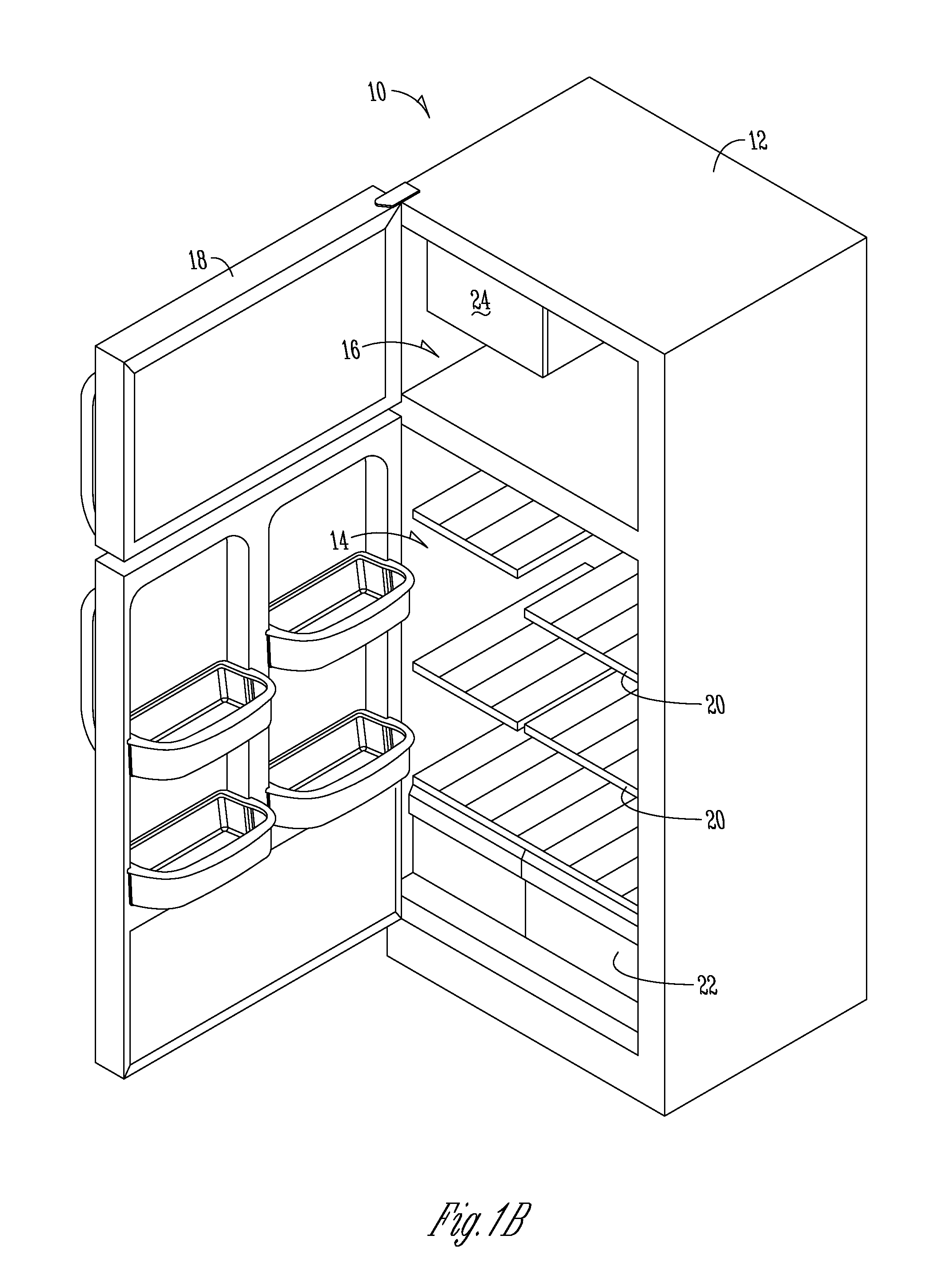
[0032]FIGS. 1A and 1B illustrate refrigerators 10 in accordance with exemplary embodiments of the present disclosure. Each of the refrigerators 10 is comprised of a refrigerator cabinet 12. FIG. 1A illustrates a refrigerator 10 with the fresh food compartment 14 is disposed above the freezer compartment 16, commonly referred to as a “bottom mount” refrigerator. A user may access the fresh food compartment 14 through one or more doors 18. In the exemplary embodiment of FIG. 1A, two French doors are shown. In the bottom mount configuration, a user may access the freezer compartment 16 by slidably opening a drawer 19. FIG. 1B illustrates a refrigerator 10 with the freezer compartment 16 is disposed above the fresh food compartment 16, commonly referred to as a “top mount” refrigerator. In both the bottom mount and top mount configurations, the fresh food section 14 may be comprised of any number of shelves 20 and drawers 22 commonly known in the art. Furthermore, in both the bottom mou...


PUM


Abstract

An improved defrost chamber is disposed with the freezer compartment of a refrigerator, removing the need to relocate a food item prior to thawing. The defrost chamber has at least one wall configured to heat the interior. A control unit is in electric communication with and adapted to supply a voltage to the wall(s). The control unit has a timer to initiate or terminate the defrosting operation. The wall(s) may comprise a glass panel associated with electrically conductive material. The control unit may independently control the heat supplied to each of the walls. The control unit may be remotely controllable by a user. One or more vents associated with the defrosting chamber may be open in a non-use configuration and closed in a use configuration. The defrost chamber may be removable from the freezer compartment.

Description

FIELD OF THE DISCLOSURE[0001]The present disclosure relates generally to defrosting of frozen food items. More particularly, but not exclusively, the present disclosure relates to a glass defrost chamber within a freezer compartment.BACKGROUND OF THE DISCLOSURE[0002]Refrigeration and freezing are extremely popular forms of food preservation. In the case of freezing, food is maintained at below-freezing temperatures at approximately 0° F. (−18° C.), which among other things, renders microbes (e.g., bacteria, yeast, molds, etc.) inactive. In particular, freezing food keeps it safe by slowing the movement of molecules, causing the microbes to enter a dormant stage. Freezing food also prevents spoilage and prolongs the shelf life by slowing down the breakdown of cell enzymes in the food.[0003]Many frozen food items are often defrosted prior to cooking. In particular, most proteins such at beef, poultry, pork, fish, and the like, become quite hardened while frozen. Properly defrosting th...

Claims


Application Information

Patent Timeline
IPC IPC(8): F25D21/08
CPCF25D21/08F25D23/12F25D25/025F25D29/00F25D31/005F25B2600/07
Inventor MILLETT, FREDERICK A.
Owner WHIRLPOOL CORP
Learn More