
Device to couple members of a heavy-duty machine

a technology for heavy-duty machines and boom frames, which is applied in mechanical machines/dredgers, soil-shifting machines/dredgers, construction, etc., can solve the problems of time-consuming and potentially dangerous, adverse impact on individual excavavator efficiency, and associated increase of job costs, so as to optimize subcomponent performance, efficient couple boom frames to stick frames, and quick coupling and decoupling

Pending Publication Date: 2022-02-24
GILMORE WORK TOOLS INC D B
View PDF0 Cites 0 Cited by
  • Summary
  • Abstract
  • Description
  • Claims
  • Application Information

AI Technical Summary

Benefits of technology

The invention is an adaptive coupler that improves the efficiency and flexibility of attaching a boom and stick with a tool. It allows for quick coupling and decoupling, and provides a safe, durable, and cost-effective solution. The coupler includes coupling elements carried by the coupling members for connecting a source of power from the machine to the stick or tool, ensuring the proper mating of the coupling elements when the coupling members of the stick and boom are brought into engaging relation. Overall, the invention provides a better and more versatile attachment for heavy-duty machines and tools.

Problems solved by technology

As the diversity and complexity of new construction operations expanded over time, demands on the utility of the excavator grew quickly as well.
Swapping work tools for an excavator involves removal and replacing of steel pins and the coupling / uncoupling of hydraulic lines, both of which are time consuming and potentially dangerous.
The requirement for increased excavator system numbers creates a downside impact on individual excavator efficiency and associated increase in job costs.
Although the concept significantly broadens versatility of the excavator, the third member location of the coupler mass does limit the size of viable work tools for construction jobs.
Increasing coupler size to accommodate larger work tools leads to excessive loads on the excavator system, thus limiting applications of the bucket coupler concept to the smaller excavator classes.
Couplers commonly known in the art have yet to solve these issues.
For example, the coupler systems disclosed in U.S. Pat. Nos. 4,938,651, 5,108,252, 5,360,313, 5,484,250, 6,301,811, and 6,428,265 represent permissible system with respect to expected second member coupler performance standards however are in no way optimal configuration designs.
Much of the non-optimal character stems from the fact that several subcomponents are inherently inferior in the context of their contribution to overall system performance.
These subcomponents were badly synthesized and / or improperly sized to perform optimal function for coupler operation.

Method used


Image

  • Device to couple members of a heavy-duty machine
  • Device to couple members of a heavy-duty machine
  • Device to couple members of a heavy-duty machine

Examples


Embodiment Construction

Definitions—Introductory Matters

[0071]The following definitions and introductory matters are provided to facilitate an understanding of the present invention. Unless defined otherwise, all technical and scientific terms used herein have the same meaning as commonly understood by one of ordinary skill in the art to which embodiments of the present invention pertain.

[0072]The terms “a,”“an,” and “the” include both singular and plural referents.

[0073]The term “or” is synonymous with “and / or” and means any one member or combination of members of a particular list.

[0074]The terms “invention” or “present invention” as used herein are not intended to refer to any single embodiment of the particular invention but encompass all possible embodiments as described in the specification and the claims.

[0075]The term “about” as used herein refers to slight variations in numerical quantities with respect to any quantifiable variable. One of ordinary skill in the art will recognize inadvertent error...


PUM


Abstract

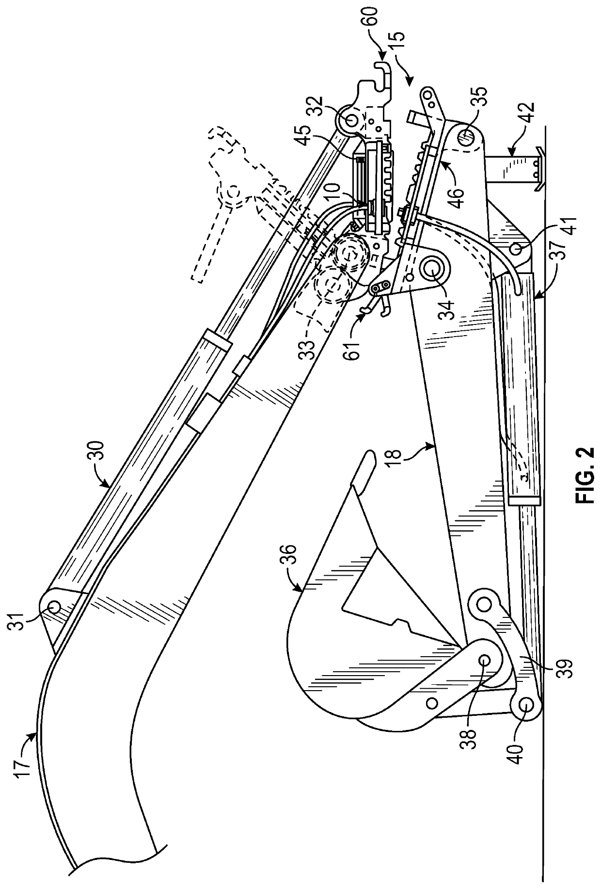
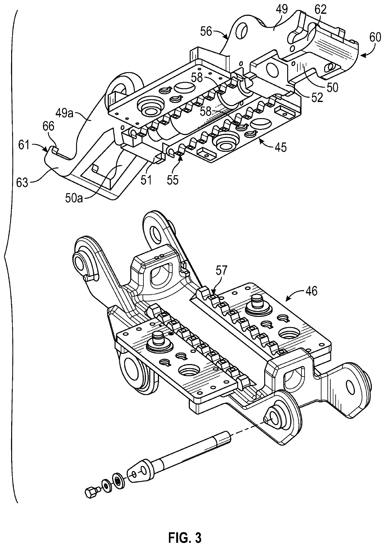
A coupler system to facilitate carrying or operating a working tool is provided. For example, a boom frame is rotated about a master pin location to mate with a stick frame at a picker end and coupled to the stick frame with a latching or locking mechanism. The boom frame is further rotated about the master pin location to mate with the stick frame at a grabber end opposite the picker end coupled to the stick frame with an additional latching or locking mechanism. Static stresses are then pre-loaded onto a pulling mechanism which secures the boom frame to the stick frame to prevent failure and dynamic stresses are dispersed onto a compression mechanism to mitigate fatigue. Hydraulic fluid is passed between the boom frame and the stick frame to maintain cleanliness in a hydraulic valve environment while coupling the stick frame to the boom frame.

Description

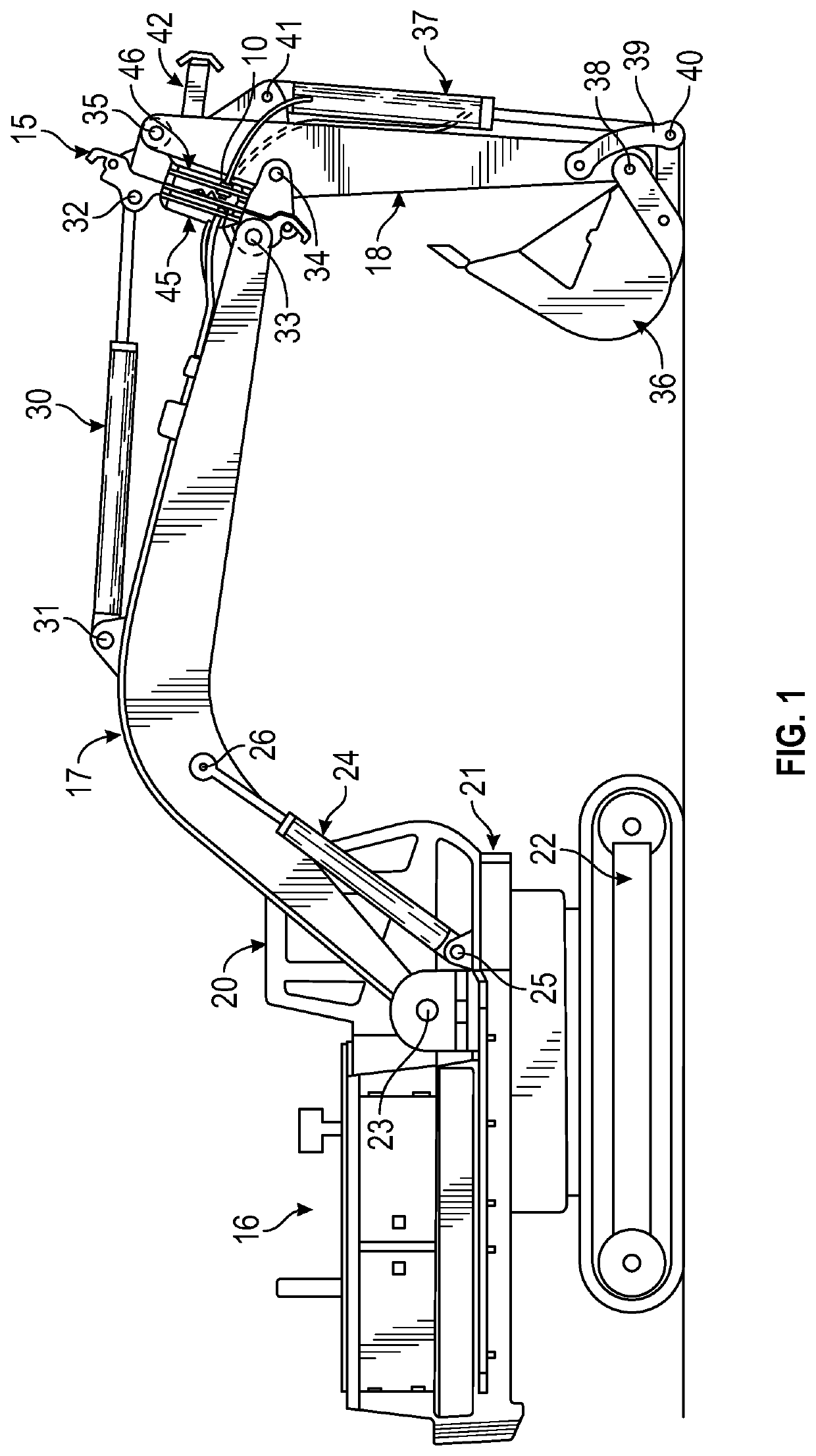
FIELD OF THE INVENTION[0001]The present invention relates generally to a coupling device and corresponding method of use in at least the construction and heavy equipment industries.BACKGROUND OF THE INVENTION[0002]An excavator is a construction vehicle used to facilitate work tool operations on various natural and man-made elements in our environment, to include such tasks as earth moving, demolition of structures, material handling, general grading / landscaping, forestry work, lifting and placing of pipes, mining, and river dredging. Excavators come in a wide range of sizes and capacities depending upon the type and general magnitude of the scheduled excavator task. The excavator incorporates three basic parts: a prime mover, a powerful boom arm, and a stick. The prime mover comprises a diesel engine that burns fuel to provide power for excavator operations. The boom arm is used to position the stick to which the work tool is attached. These components connect by means of a series o...

Claims


Application Information

Patent Timeline
IPC IPC(8): E02F3/36E02F3/30
CPCE02F3/3663E02F3/30E02F3/3622E02F3/369E02F3/3654E02F3/3636E02F3/3631E02F3/364
Inventor ARNOLD, DAVIDASJES, DAVIDPIETIG, PAULVOGEL, JERRY
Owner GILMORE WORK TOOLS INC D B
Learn More