Rotatable nacelle for centrifugal fan on aircraft

a centrifugal fan and nacelle technology, which is applied in the direction of vertical landing/take-off aircraft, power plant exhaust arrangement, transportation and packaging, etc., can solve the problems of inability to and inability to fully utilize the power of the airframe, etc., to achieve efficient harnessing, increase the use of air taxis, and provide stability for the airframe

Pending Publication Date: 2021-10-28
SHEIL JERROLD JOSEPH
View PDF18 Cites 0 Cited by
  • Summary
  • Abstract
  • Description
  • Claims
  • Application Information

AI Technical Summary

Benefits of technology

[0013]An aspirational object, feature, and/or feature of the present invention is to increase the use of air taxis throughout the world. It is thus envisioned, albeit not required, that the present invention be implemented on ultralight airplanes. Such airplanes could include private planes, remote control planes, drones, and the like. Some commercial aircraft could still stand to benefit by incorporating this concept.
[0014]It is a further object, feature, and/or advantage of the present invention to produce a byproduct flywheel effect via the high speed rotating mechanical apparatus so as to provide stability for the airframe while airborne. For example, it is desirable to always maintain any propeller(s) on the aircraft in a constant, upright position.
[0015]It is still yet a further object, feature, and/or advantage of the present invention to provide

Problems solved by technology

Traditional vertical takeoff and landing (VTOL) and short takeoff and landing (STOL) aircraft are inherently unstable.
The inherent instability comes from disrupting with an external torque, the naturally stable position of the rotating object (propeller), which has massive angular momentum during rotation.
If secondary rotation were not permitted, and instead the axial member were mechanically connected to another object were introduced, the components of the bicycle wheel assembly could fail.
Traditional vertical takeoff and landing (VTOL) and short takeoff and landing (STOL) thus often crash because they require extreme manipulation of torque to reposition thrust from a vertical force to a propelling horizontal force while the propeller is rotating at a high speed.
As an example, the Bell

Method used


Image

  • Rotatable nacelle for centrifugal fan on aircraft
  • Rotatable nacelle for centrifugal fan on aircraft
  • Rotatable nacelle for centrifugal fan on aircraft

Examples


Embodiment Construction

[0043]The present disclosure is not to be limited to that described herein. Mechanical, electrical, chemical, procedural, and / or other changes can be made without departing from the spirit and scope of the present invention. No features shown or described are essential to permit basic operation of the present invention unless otherwise indicated.

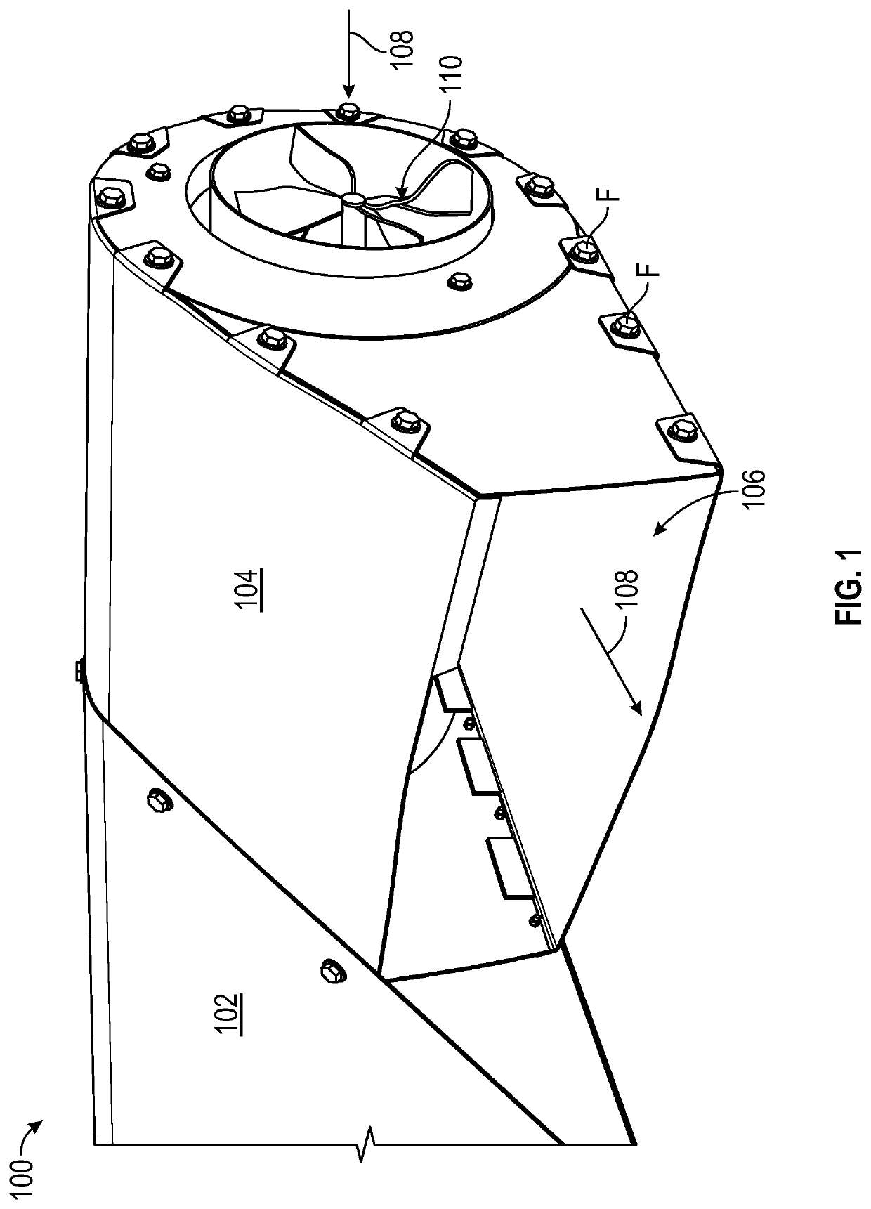
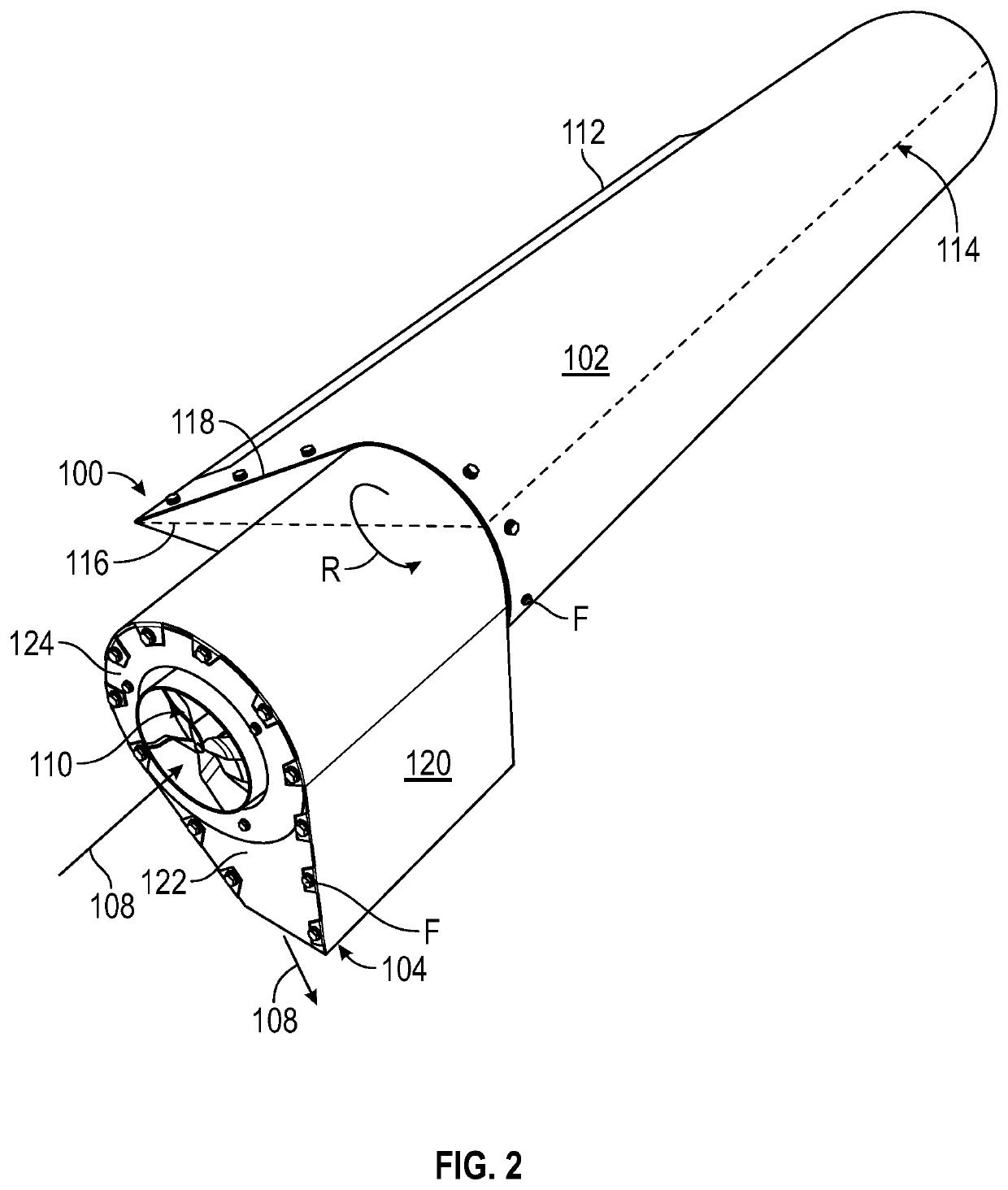
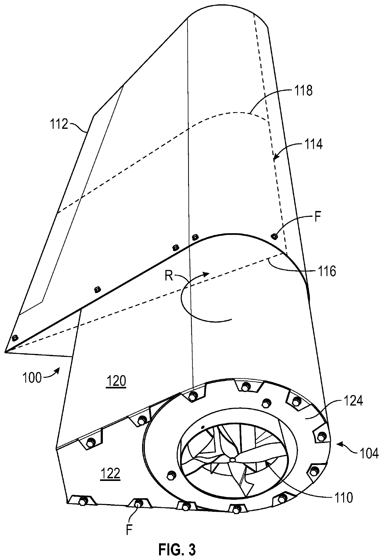
[0044]Referring now to the figures, an aircraft 98 can be equipped with a self-contained wing, fan, and nacelle assembly 100, as shown in FIG. 1. The wing, fan, and nacelle assembly 100 is shown including the wing 102, nacelle 104, fan 110. When operated, the fan 110 and nacelle allow air to enter the nacelle 104, turn approximately ninety degrees, and exit the nacelle 104 via a discharge nozzle 106. The nacelle 104 is preferably rotatable.

[0045]The wing 102 acts as a type of fin that produces lift while moving through air or some other fluid. The wing 102 can be defined by a trailing edge 112, a leading edge 114, a chord 116 joining the lea...


PUM


Abstract

An aircraft achieves vertical takeoff and landing and short takeoff and landing capabilities by transitioning the thrust created by a super charged centrifugal fan from a vertical launch position to a horizontal cruise position for a resulting propulsion effect. Neither the rotors or the engines included on the aircraft have to move or rotate into a distinct position in order to provide such vertical takeoff and landing and short takeoff and landing capabilities.

Description

CROSS REFERENCE TO RELATED APPLICATIONS[0001]This application claims priority under 35 U.S.C. § 119 to provisional patent application U.S. Ser. No. 63 / 101,272, filed Apr. 22, 2020. The provisional patent application is herein incorporated by reference in its entirety, including without limitation, the specification, claims, and abstract, as well as any figures, tables, appendices, or drawings thereof.FIELD OF THE INVENTION[0002]The present invention relates generally to an apparatus and / or corresponding method of use in at least the aerospace industry. More particularly, but not exclusively, the present invention relates to a rotatable nacelle for a centrifugal fan on an aircraft.BACKGROUND OF THE INVENTION[0003]The background description provided herein gives context for the present disclosure. Work of the presently named inventors, as well as aspects of the description that may not otherwise qualify as prior art at the time of filing, are neither expressly nor impliedly admitted a...

Claims


Application Information

Patent Timeline
IPC IPC(8): B64C29/00B64D33/02B64D33/04B64D29/02B64C3/14B64C9/00B64D29/06B64C39/02B64D27/24
CPCB64C29/0033B64D33/02B64D33/04B64D29/02B64C3/14B64C5/02B64D29/06B64C39/024B64D27/24B64C2009/005B64C2203/00B64C9/00B64C29/0016
Inventor SHEIL, JERROLD JOSEPH
Owner SHEIL JERROLD JOSEPH
Why Eureka
Try Eureka