Transmission-type display

Active Publication Date: 2016-11-03
SEIKO EPSON CORP
View PDF27 Cites 25 Cited by
  • Summary
  • Abstract
  • Description
  • Claims
  • Application Information

AI Technical Summary

Benefits of technology

[0020]In still another aspect of the invention, the transmission type display further includes a flip-up mechanism that flips up the pair of left and right display devices so

Problems solved by technology

Here, although the see-through type HMD is roughly divided into a single-eye type HMD that projects the image light to one eye, and a both-eye type HMD that projects the image light to both eyes, since humans estimate the distance from the image light to be projected in the single-eye type, it is considered that there is a case where it is difficult to feel th

Method used


Image

  • Transmission-type display
  • Transmission-type display
  • Transmission-type display

Examples


Example

[0034]Hereinafter, a transmission-type display according to a first embodiment of the invention will be described in detail with reference to FIG. 1 and the like.

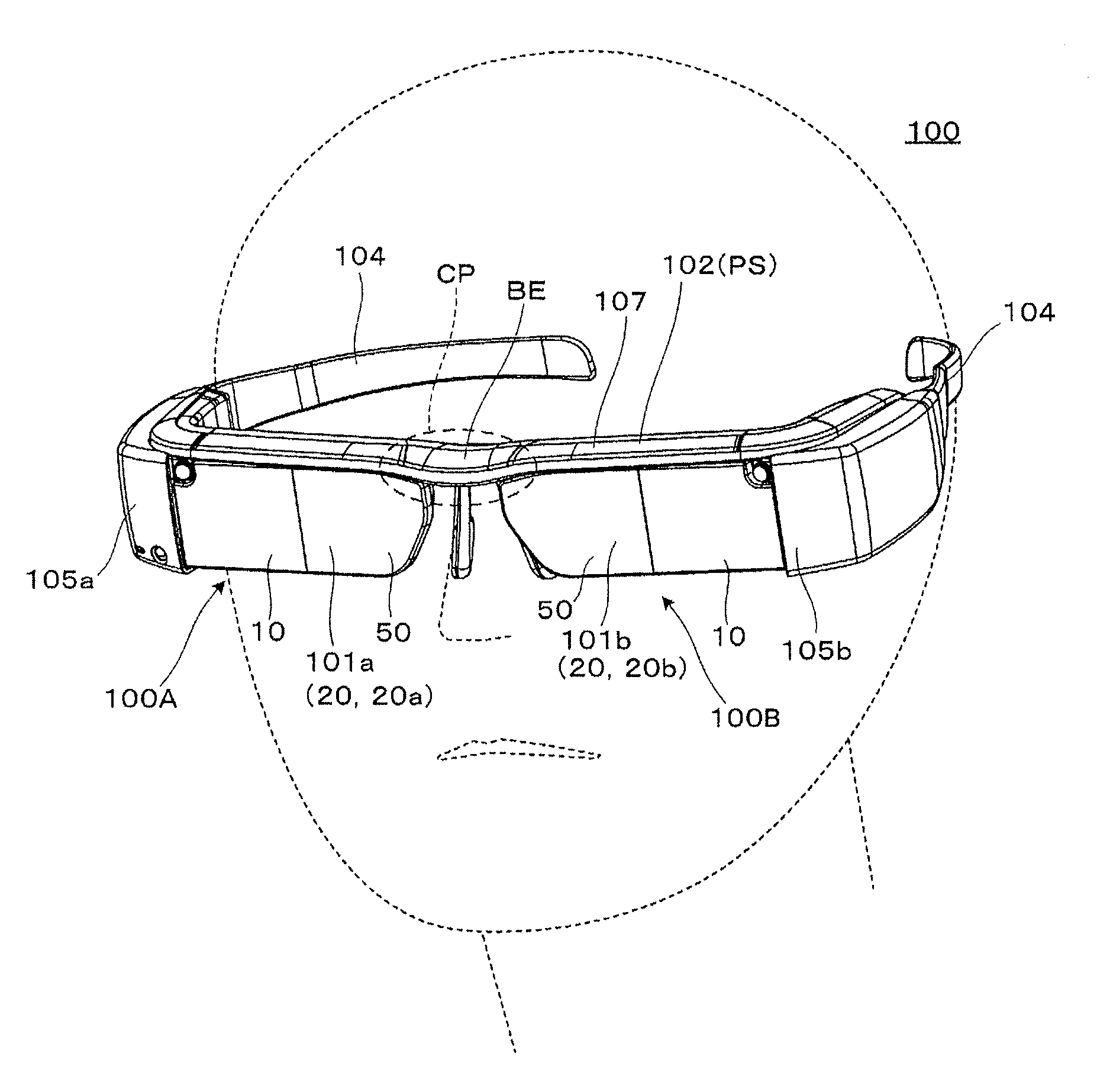
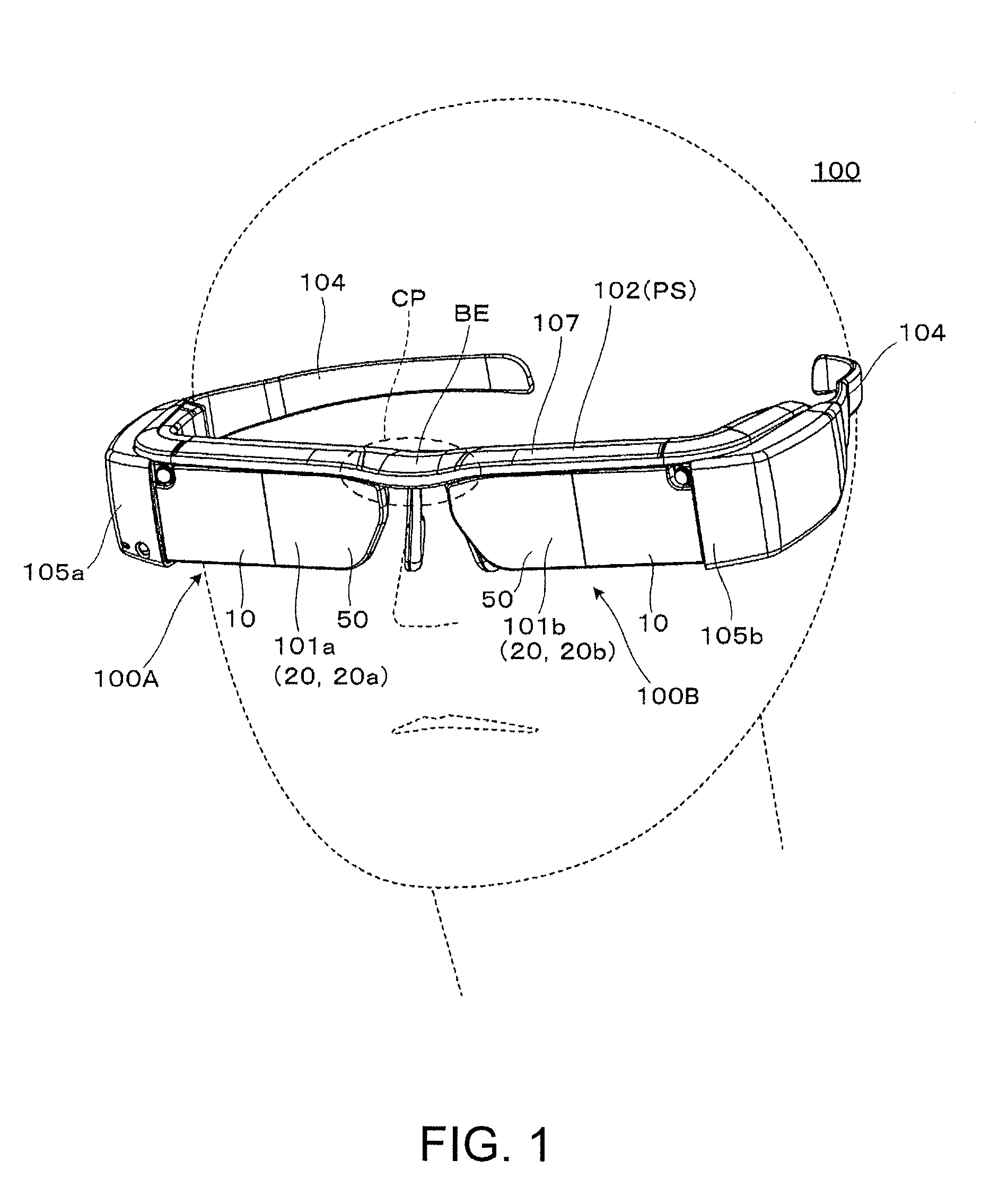
[0035]As described in FIGS. 1 and 2, the transmission-type display 100 of the present embodiment is a head mount display having an appearance such as glasses, and is a transmission-type display allowing the observer or the user wearing the transmission-type display 100 to visually recognize image light of a virtual image, and the observer to visually recognize or to observe an image of the outside world in a see-through manner. The transmission-type display 100 includes first and second optical members 101a, 101b that cover the front of the eyes of the observer while allowing transparency, a frame unit 102 that supports both optical members 101a, 101b, and first and second image forming body units 105a, 105b that are added to parts from the left and right ends of the frame unit 102 to a handle portions (temples) 104 in the ...

Example

Second Embodiment

[0057]Hereinafter, a transmission-type display according to a second embodiment will be described. Further, the present embodiment is a modification example of the transmission-type display of the first embodiment, and is the same as in the case of the first embodiment except for the image control in the image display device 80, such that the entire illustration and description will be omitted.

[0058]FIGS. 6A and 6B are diagrams illustrating the image control in the image display device 80 of the transmission-type display according to this embodiment, and FIG. 6A is a diagram illustrating a part of the internal structure of a transmission-type display of this embodiment. As illustrated in FIG. 6A, the transmission-type display of this embodiment includes image display devices 80a, 80b which are image display devices 80 respectively disposed in first and second display devices 100A, 100B which are provided on the left and right in a pair (see FIG. 1), and an image con...

Example

Third Embodiment

[0062]Hereinafter, a transmission-type display according to a third embodiment will be described. Further, the transmission-type display of the present embodiment is a modification example of the transmission-type displays of the above respective embodiments, and is different from the cases of the above respective embodiments in including an angle changing unit that changes the postures of the pair of left and right display devices, and a focusing mechanism that focuses the projection lens. In addition, the present embodiment is the same as in the case of the first embodiment and the like for the structure other than the angle changing unit and the focusing mechanism, such that the entire illustration and description will be omitted.

[0063]FIG. 7 is a cross-sectional view of a body portion of the transmission type display device according to the present embodiment in a plan view, and is a diagram corresponding to FIG. 2. In the present embodiment, first, as illustrate...


PUM


Abstract

In first and second display devices that are provided in a pair on the left and right sides, image light and external light are superimposed on each other and viewed. In this case, a parallax of an angle (the value of angle) is set by a frame unit functioning as a parallax setting unit tilting principal rays of left and right image light inwardly, and the angle of convergence of an observer is in an appropriate state in the case of viewing the image light.

Description

BACKGROUND[0001]1. Technical Field[0002]The present invention relates to a transmission-type display such as a head mount display that presents an image formed by an image display element or the like to an observer.[0003]2. Related Art[0004]In a transmission-type display such as a head mount display (hereinafter, also referred to as a HMD) that is mounted on the head of the observer, development of augmented reality sensation (hereinafter, also referred to as AR or augmented reality) in which image light is superimposed on a world that is viewed in the real field of view is expected. For example, a technique of determining a distance to an object of interest of the user by using a focusing mechanism of a camera such that the position of the image is consistent with the position of the real world, and performing an image shift of an appropriate amount on the image that is displayed on the display device provided in front of the eye, in order to make a modification on the difference b...

Claims


Application Information

Patent Timeline
IPC IPC(8): G02B27/01H04N13/04H04N13/00
CPCG02B27/0179G02B27/0172G02B27/0176H04N13/0022H04N13/044H04N13/0497H04N13/0484G02B2027/0134G02B2027/0181G02B2027/0185G02B2027/014G02B2027/0159G02B2027/0156G02B2027/0138H04N13/128H04N13/344H04N13/383H04N13/398
Inventor MIYAO, TOSHIAKITAKAGI, MASAYUKIKOMATSU, AKIRATOTANI, TAKAHIROTAKEDA, TAKASHI
Owner SEIKO EPSON CORP
Why Eureka
Try Eureka