
Programmable Vision Accelerator

a vision accelerator and programming technology, applied in the field of computer processing, can solve the problems of sacrificing flexibility or performance, many cpus are unable to meet the performance requirements of many computer vision applications, and many cpus are unable to execute complex object detection algorithms in real-time,

Active Publication Date: 2016-11-03
NVIDIA CORP
View PDF3 Cites 67 Cited by
  • Summary
  • Abstract
  • Description
  • Claims
  • Application Information

AI Technical Summary

Benefits of technology

The disclosed techniques allow computer vision applications to meet performance requirements without sacrificing flexibility or performance. This is a big advantage as it allows for a wider range of applications to use these techniques.

Problems solved by technology

However, CPUs are oftentimes unable to meet the performance requirements of many computer vision applications, such as those related to execution time and power consumption, for example.
In particular, many CPUs are unable to execute complex object detection algorithms in real-time, which is a requirement of in-vehicle ADAS applications.
One drawback of specialized hardware units, however, is that many such units have to be configured using low-level programming techniques.
Accordingly, configuring specialized hardware units to implement a wide variety of computer vision algorithms across a wide breadth of visual data is impractical, if not impossible.
If a computer vision algorithm requires more nested loops than a particular hardware unit allows, then the computer vision algorithm cannot execute on the hardware unit.

Method used


Image

  • Programmable Vision Accelerator
  • Programmable Vision Accelerator
  • Programmable Vision Accelerator

Examples


Embodiment Construction

[0017]In the following description, numerous specific details are set forth to provide a more thorough understanding of the present invention. However, it will be apparent to one of skill in the art that the present invention may be practiced without one or more of these specific details.

System Overview

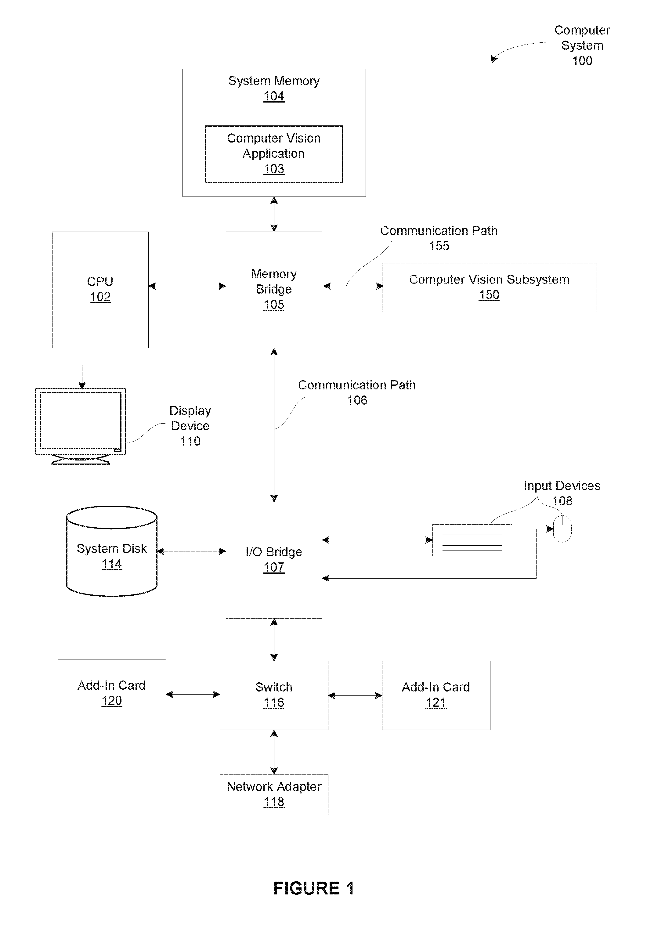
[0018]FIG. 1 is a block diagram illustrating a computer system 100 configured to implement one or more aspects of the present invention. As shown, computer system 100 includes, without limitation, a central processing unit (CPU) 102 and a system memory 104 coupled to a computer vision subsystem 150 via a memory bridge 105 and a communication path 155. The memory bridge 105 is further coupled to an I / O (input / output) bridge 107 via a communication path 106, and the I / O bridge 107 is, in turn, coupled to a switch 116.

[0019]In operation, the I / O bridge 107 is configured to receive user input information from input devices 108, such as a keyboard or a mouse, and forward the input informat...


PUM


Abstract

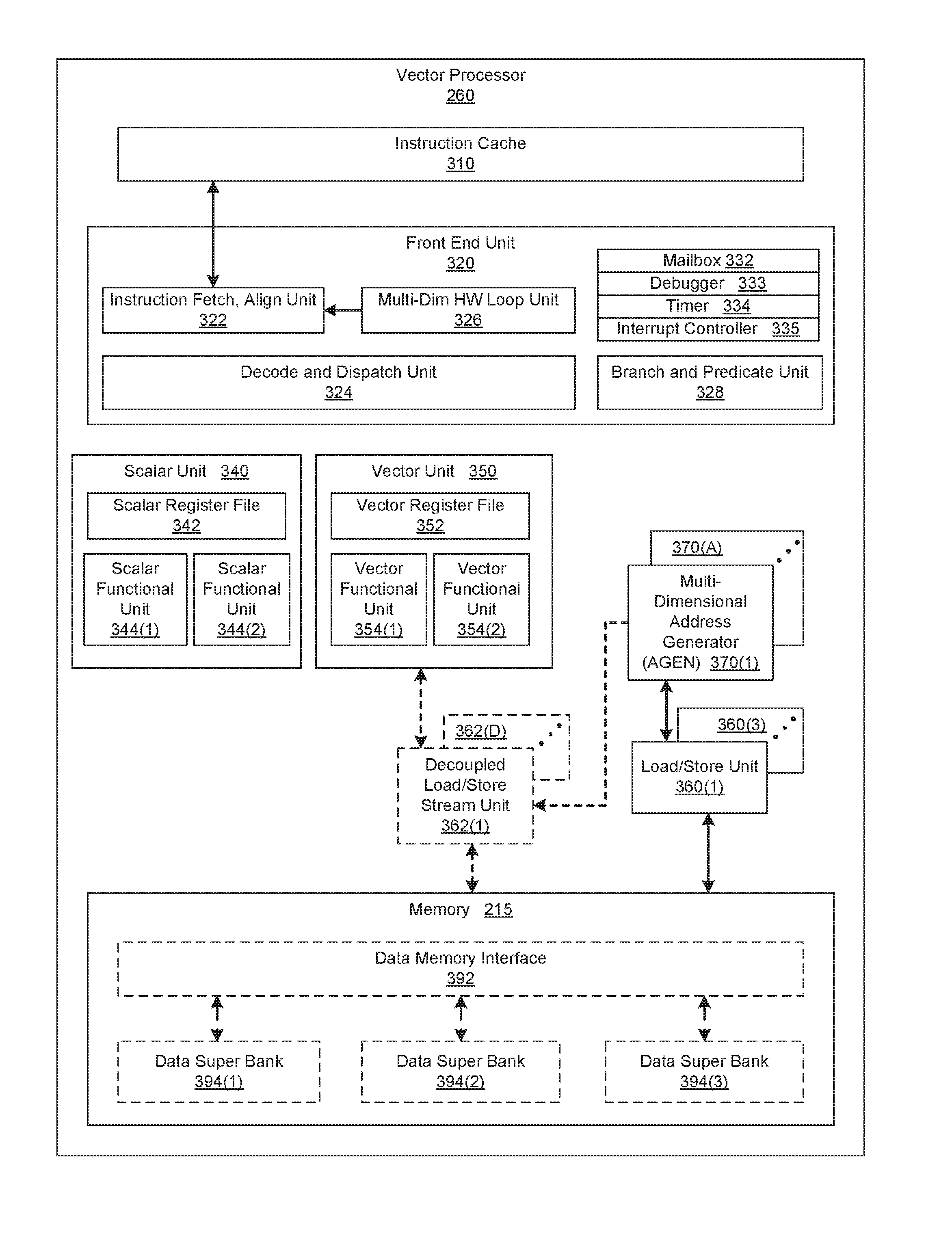
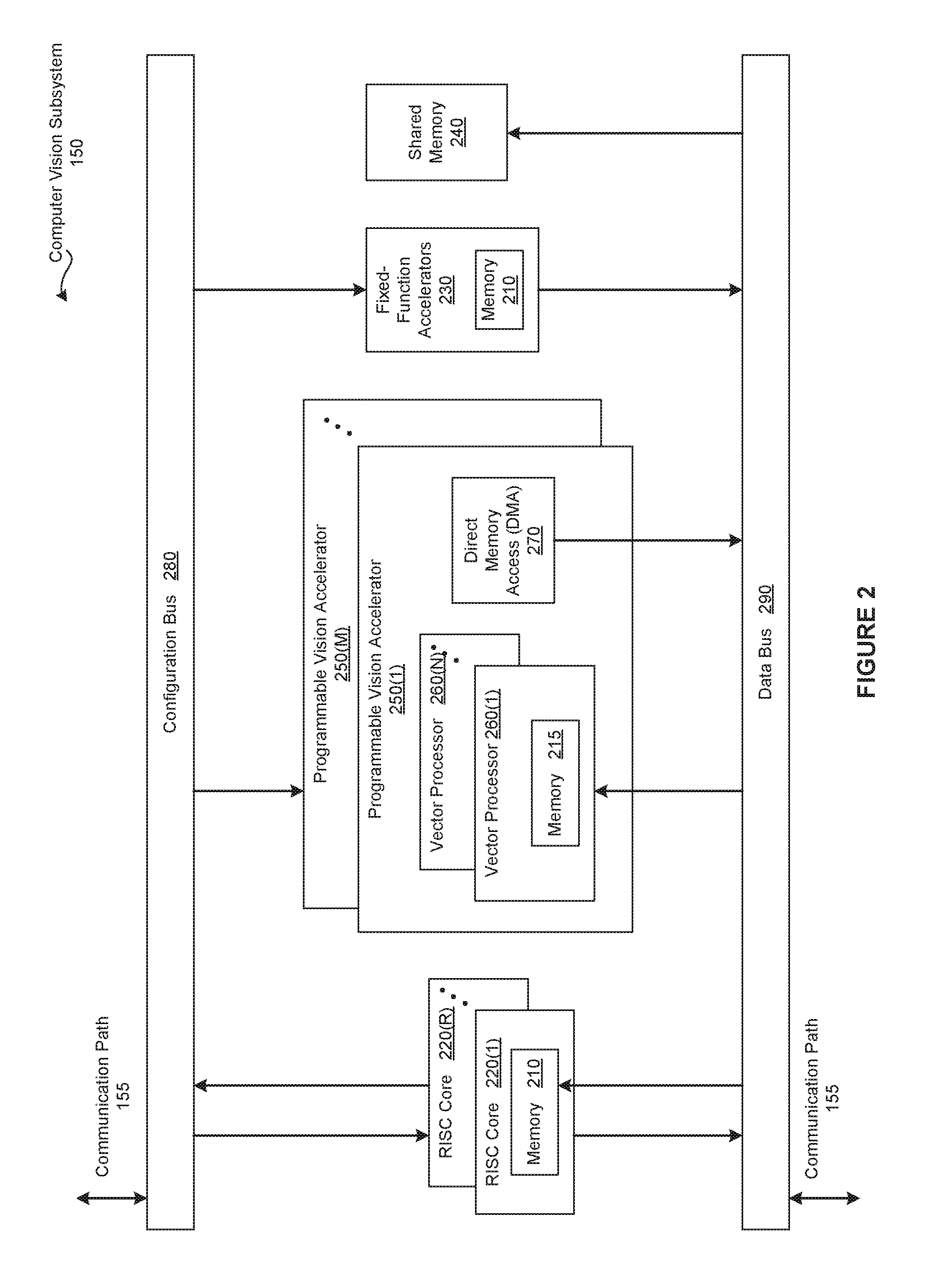
In one embodiment of the present invention, a programmable vision accelerator enables applications to collapse multi-dimensional loops into one dimensional loops. In general, configurable components included in the programmable vision accelerator work together to facilitate such loop collapsing. The configurable elements include multi-dimensional address generators, vector units, and load / store units. Each multi-dimensional address generator generates a different address pattern. Each address pattern represents an overall addressing sequence associated with an object accessed within the collapsed loop. The vector units and the load store units provide execution functionality typically associated with multi-dimensional loops based on the address pattern. Advantageously, collapsing multi-dimensional loops in a flexible manner dramatically reduces the overhead associated with implementing a wide range of computer vision algorithms. Consequently, the overall performance of many computer vision applications may be optimized.

Description

CROSS-REFERENCE TO RELATED APPLICATIONS[0001]This application claims benefit of the United States Provisional Patent Application having Ser. No. 62 / 156,167 (Attorney Docket Number 15-SC-0128-US0) and filed on May 1, 2015. The subject matter of this related application is hereby incorporated herein by reference.BACKGROUND OF THE INVENTION[0002]1. Field of the Invention[0003]Embodiments of the present invention relate generally to computer processing and, more specifically, to a programmable vision accelerator.[0004]2. Description of the Related Art[0005]Computer vision is the process of automatically perceiving, analyzing, understanding, and / or interpreting visual data. Such visual data may include any combination of videos, images, real-time or near real-time data captured by any type of camera or video recording device, and the like. Computer vision applications implement computer vision algorithms to solve high level problems in a variety of fields. For example, an advanced driver...

Claims


Application Information

Patent Timeline
Patent Type & Authority Applications(United States)
IPC IPC(8): G06F9/30G06F15/82
CPCG06F9/30065G06F15/82G06F9/30036G06F9/3001G06F9/30072G06F9/3013G06F9/325G06F9/342G06F9/345G06F9/383G06F15/8061G06F12/0207
Inventor HUNG, CHING Y.SANKARAN, JAGADEESHSINGH, RAVI P.TZENG, STANLEY
Owner NVIDIA CORP
Learn More