Antenna system and harmonic suppression element

a harmonic suppression element and antenna system technology, applied in the field of antenna systems, can solve the problems of aggregation requiring multiple frequency ranges and a wide frequency range width

Active Publication Date: 2016-11-03
MEDIATEK INC
View PDF6 Cites 6 Cited by
  • Summary
  • Abstract
  • Description
  • Claims
  • Application Information

AI Technical Summary

Benefits of technology

[0084]The embodiments of the disclosure propose a novel antenna system with frequency dividing circuits. Each frequency dividing circuit may be implemented with a low-pass filter, a high-pass filter, a band-pass filter, a diplexer, duplexer, tri-plexer, quad-plexer, or a combination thereof. With such a design, low / medium / high-frequency components do not tend to negatively affect each other, and the harmonic interference in the antenna system can be effectively eliminated. In comparison with the conventional design, the embodiments of the disclosure may provide at least one of the following advantages: (1) widening the bandwidth of an antenna system for carrier aggregation, (2) suppressing the harmonic interference in the antenna system, (3) simplifying the structure of the control circuits of the antenna system, and (4) reducing the manufacturing cost of the antenna system.

Problems solved by technology

However, the technology of carrier aggregation requires multiple frequency ranges and a wide frequency range width.
It has become a critical challenge for engineers to design such an antenna system to meet the requirements of carrier aggregation.

Method used


Image

  • Antenna system and harmonic suppression element
  • Antenna system and harmonic suppression element
  • Antenna system and harmonic suppression element

Examples


Embodiment Construction

[0055]In order to illustrate the purposes, features and advantages of the invention, the embodiments and figures of the invention will be described in detail as follows.

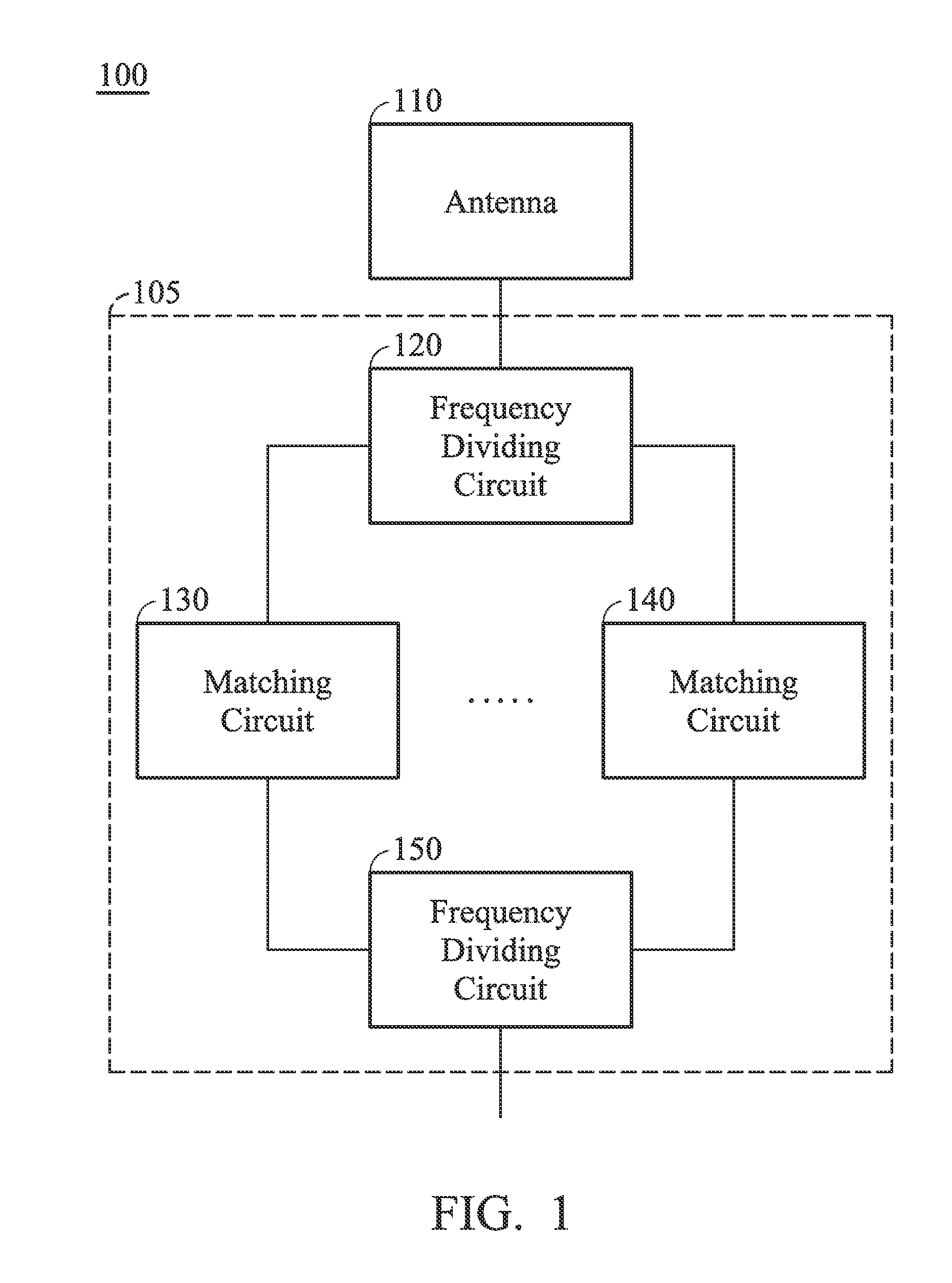
[0056]FIG. 1 is a diagram of an antenna system 100 according to an embodiment of the invention. For example, the antenna system 100 may be applied in a communication device, such as a smartphone, a tablet computer, or a notebook computer. The antenna system 100 can support the technology of carrier aggregation in the field of LTE-A (Long Term Evolution -Advance). As shown in FIG. 1, the antenna system 100 includes an antenna 110, a first frequency dividing circuit 120, a plurality of matching circuits as exemplarily shown two matching circuits 130 and 140 but not limited thereto, and a second frequency dividing circuit 150. The antenna 110 may be a monopole antenna, a dipole antenna, a loop antenna, a helical antenna, or a chip antenna, but it is not limited thereto. The first frequency dividing circuit 120 is couple...


PUM


Abstract

An antenna system includes an antenna, a first frequency dividing circuit, a second frequency dividing circuit, and a plurality of matching circuits. The first frequency dividing circuit is coupled to the antenna. The matching circuits are coupled to the first frequency dividing circuit. The second frequency dividing circuit is coupled to the matching circuits. The matching circuits are configured to process different frequency signals, respectively.

Description

CROSS REFERENCE TO RELATED APPLICATIONS[0001]This application claims the benefit of U.S. Provisional Application No. 62 / 154,356, filed on Apr. 29, 2015, the entirety of which is incorporated by reference herein.BACKGROUND OF THE INVENTION[0002]1. Field of the Invention[0003]The disclosure generally relates to an antenna system, and more particularly, to an antenna system with a harmonic suppression element.[0004]2. Description of the Related Art[0005]To meet LTE-A (Long Term Evolution -Advance) requirements, support of transmission bandwidths that are wider than the 20 MHz bandwidth specified in 3GPP (3rd Generation Partnership Project) Release 8 / 9 is required. The preferred solution to this is carrier aggregation, which is one of the most distinctive features of 4G LTE-A. Carrier aggregation allows the expansion of effective bandwidth delivered to a user terminal through concurrent utilization of radio resources across multiple carriers. Multiple component carriers are aggregated t...

Claims


Application Information

Patent Timeline
Patent Type & Authority Applications(United States)
IPC IPC(8): H04J1/04H04L27/30H04B7/04
CPCH04J1/045H04L27/30H04B7/04H01Q5/50H01Q1/241H01Q23/00H04B1/0458H01Q21/28H01Q5/314H01Q5/335
Inventor KANG, TING-WEIYEH, SHIH-HUANG
Owner MEDIATEK INC
Why Eureka
Try Eureka