Self-propelled device

Inactive Publication Date: 2016-11-10
TOSHIBA LIFESTYLE PROD & SERVICES CORP
View PDF8 Cites 4 Cited by
  • Summary
  • Abstract
  • Description
  • Claims
  • Application Information

AI Technical Summary

Benefits of technology

[0006]The problem to be solved by the invention is to provide a self-propelled device having a marker capable of resisting hindrance of another signal transmitted to a traveling element to a signal from the marker, and of surely guiding the traveling element.
[0007]In an embodiment, a self-propelled device has a traveling element. Further, the self-propelled device has a marker guiding the traveling element. The traveling element is provided with a body case. Additionally, the traveling element includes a driving wheel rotatably provided in the body case to enable this body case to travel. Moreover, the traveling element is provided with a motor allowing the driving wheel to be rotationally driven. Further, the traveling element is provided with a traveling element-side transmitting unit for transmitting a signal including traveling element-side identification information with directivity of predetermined width. Moreover, the traveling element is provided with a traveling element-side receiving unit capable of receiving a signal with directivity wider than directivity of

Problems solved by technology

Thus, the vacuum cleaner located near the charger even at any other time than returning to the charger such as the time while cleaning may not be allowed to receive a

Method used


Image

  • Self-propelled device
  • Self-propelled device
  • Self-propelled device

Examples


first embodiment

[0017]Hereinafter, description will be given for a structure of a first embodiment with reference to the drawings.

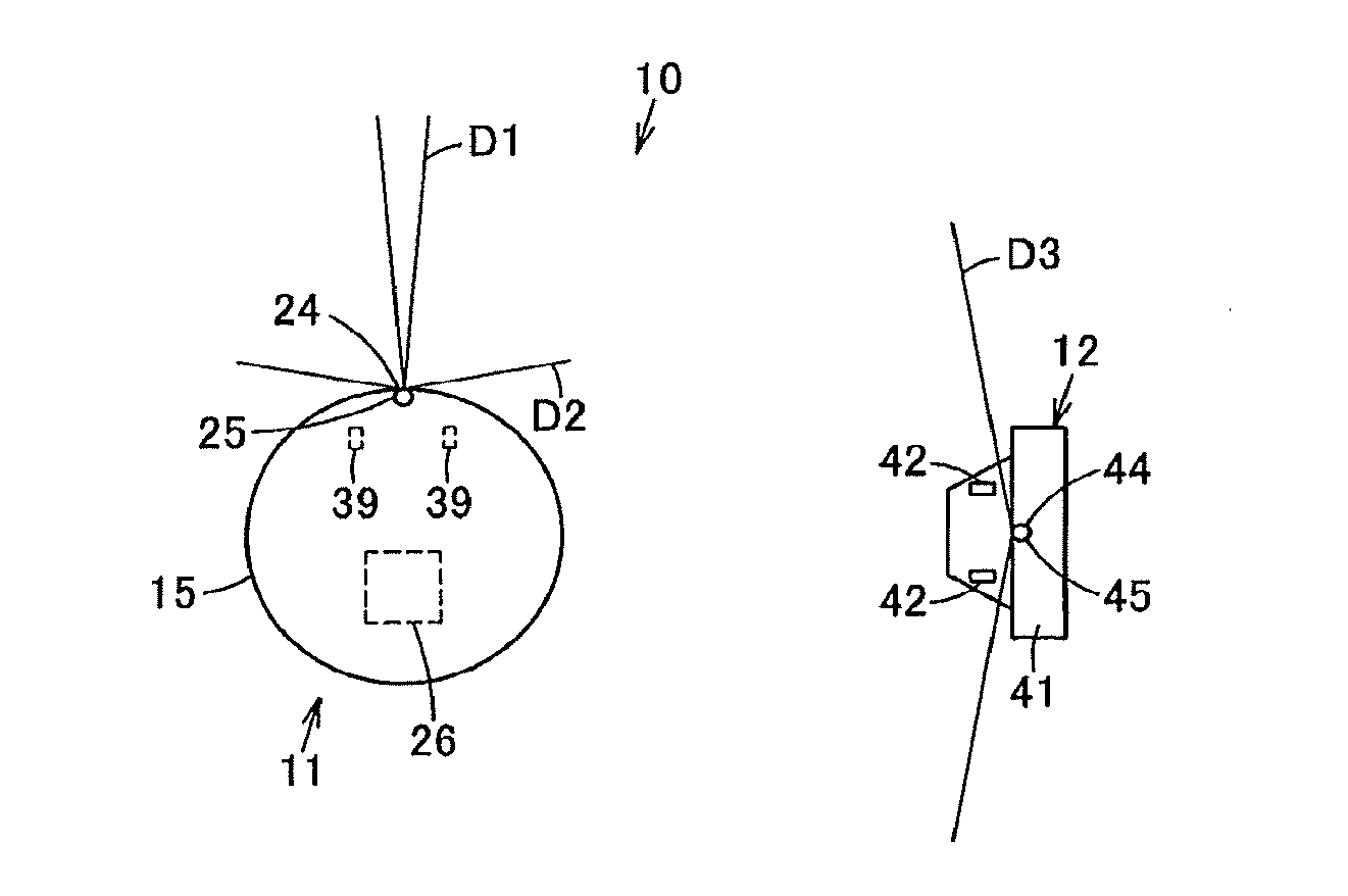
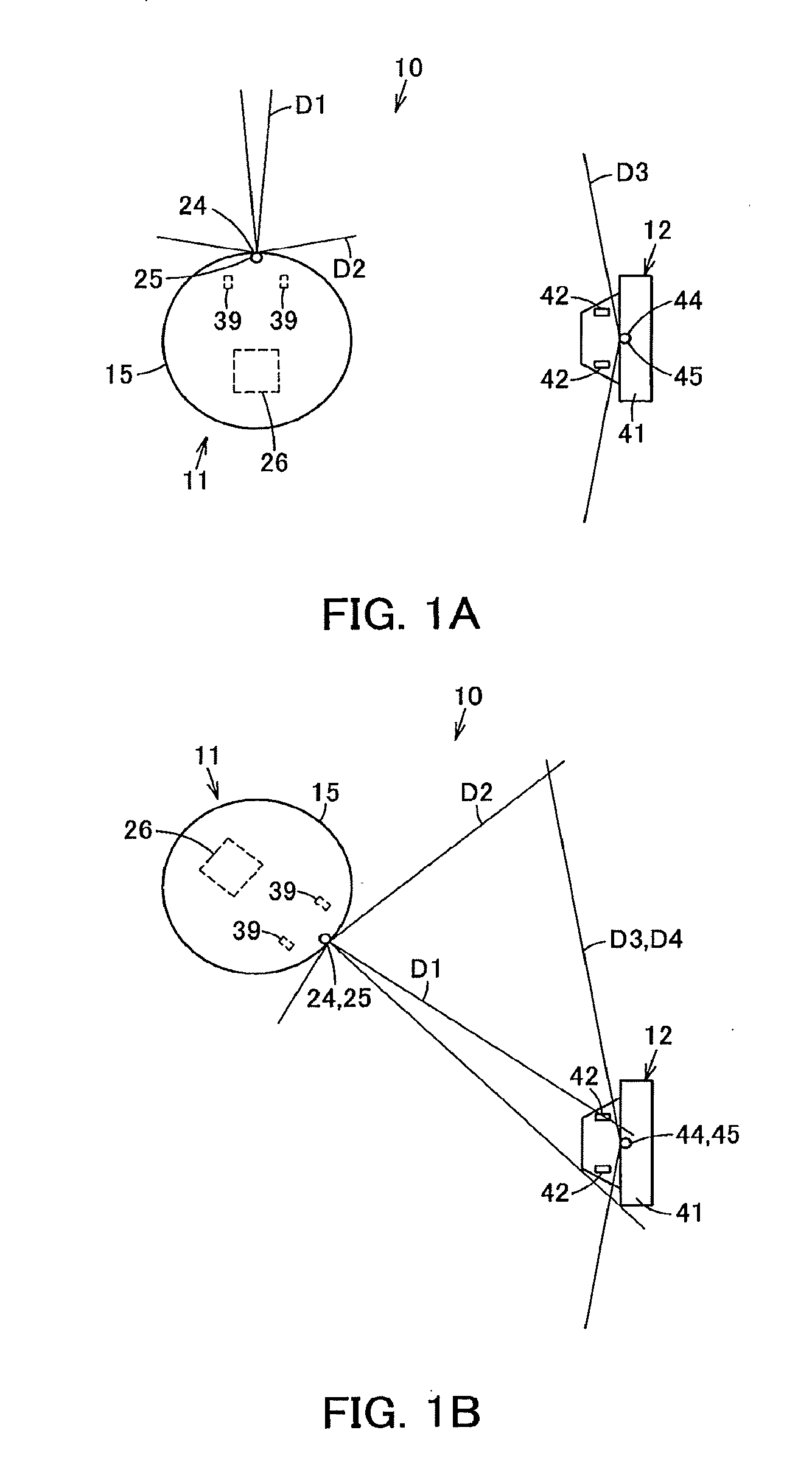
[0018]In FIGS. 1 to 4, a vacuum cleaning apparatus as self-propelled device is denoted by 10. This vacuum cleaning apparatus 10 is provided with a vacuum cleaner 11 as a traveling element, and a charger 12 as a marker capable of guiding the vacuum cleaner 11.

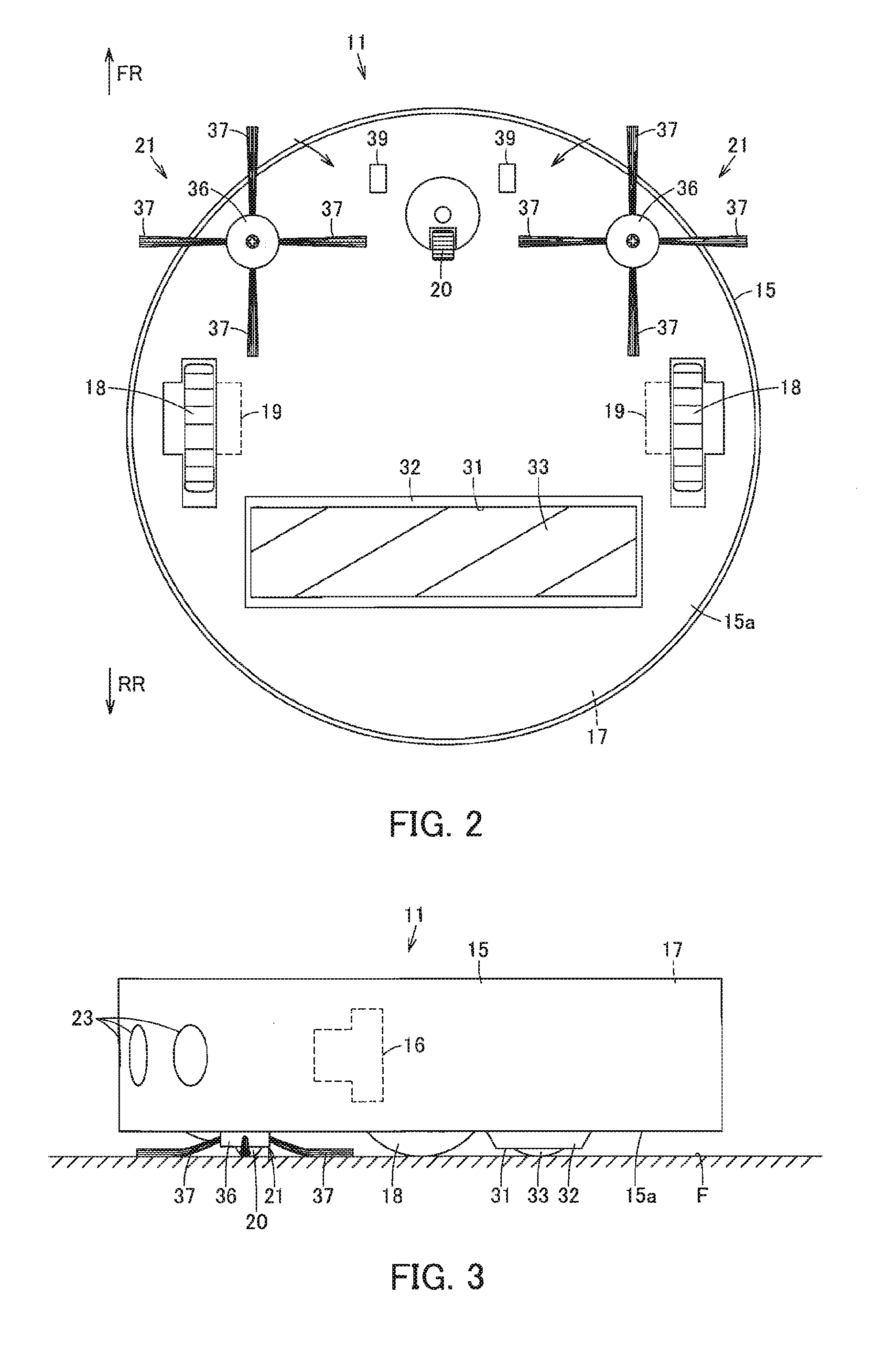
[0019]In the present embodiment, the vacuum cleaner 11 is a so-called self-propelled robot cleaner autonomously traveling (self-propelling) on the floor surface F to be cleaned while cleaning the floor surface F. Further, the vacuum cleaner 11 is provided with a hollow body case 15; an electric blower 16 as an actuating unit housed in the body case 15; a dust collection unit 17 communicating with a suction side of the electric blower 16; a plurality (a pair) of driving wheels 18, for example; a motor 19 as a driving element (driving unit) serving as an actuating unit for driving these driving wheels 18; a turning whe...

second embodiment

[0074]In the above-described second embodiment, after the vacuum cleaner 11 travels a predetermined distance based on a signal transmitted from the second transmitting unit 45 of the charger 12, when transmitting the signal from the first transmitting unit 24 again, the signal may not be transmitted by all the first transmitting units 24, but be transmitted only by the first transmitting unit 24 located in the vicinity of the travel direction of the vacuum cleaner 11 including the travel direction of the vacuum cleaner 11. That is, in a case where the vacuum cleaner 11 is allowed to travel for returning to the charger 12, once the vacuum cleaner 11 receives a signal transmitted from the second transmitting unit 45 of the charger 12 to travel, determination is made that the charger 12 is present on the side of the travel direction of the vacuum cleaner 11 and is not present on the opposite side and the like. Therefore, the first transmitting unit 24 located on the side determined tha...


PUM


Abstract

A vacuum cleaner includes a first transmitting unit transmitting a signal including first identification information with directivity of a predetermined width, and a first receiving unit receiving a signal with directivity wider than directivity of the first transmitting unit. A charger includes a second receiving unit receiving the signal including the first identification information, and a second transmitting unit transmitting a signal including second identification information when the second receiving unit receives the signal including the first identification information. A first control unit controls, when the signal including the second identification information is received by the first receiving unit, drive of a motor to allow a body case to travel based on a direction that the signal including the first identification information is transmitted.

Description

TECHNICAL FIELD[0001]The present invention relates to a self-propelled device provided with a marker for guiding the position of a traveling element.BACKGROUND ART[0002]Conventionally, a so-called self-propelled vacuum cleaner (cleaner robot) is known for detecting an obstacle and the like with use of, for example, a sensor and the like while autonomous traveling on the floor surface to be cleaned to clean the floor surface. Such a vacuum cleaner has a driving wheel for travel arranged in the bottom of a body case having a dust collection unit and the like, the driving wheel being driven by a motor actuated with power supplied from a secondary battery housed in the body case, thereby traveling on the floor surface[0003]Such the vacuum cleaner is configured to, after cleaning, return to a predetermined charger serving also as a marker guiding a traveling element for charging a secondary battery, where a signal for guiding the vacuum cleaner to the charger is always transmitted from t...

Claims


Application Information

Patent Timeline
IPC IPC(8): A47L11/40G05D1/02
CPCA47L11/4011G05D1/0225G05D1/0242A47L11/4013A47L2201/04A47L11/4069A47L11/4041G05D2201/0215A47L11/4066A47L2201/02
Inventor ABE, KOUICHI
Owner TOSHIBA LIFESTYLE PROD & SERVICES CORP
Why Eureka
Try Eureka