Liquid ejector and liquid ejecting detector

a detector and liquid ejector technology, applied in printing and other directions, can solve the problems and accumulating waste liquid, so as to achieve adequate wiping quality and prevent the ejector from ejecting. the effect of reducing the wiping quality of the wiper member

Active Publication Date: 2016-11-10
RICOH KK
View PDF3 Cites 7 Cited by
  • Summary
  • Abstract
  • Description
  • Claims
  • Application Information

AI Technical Summary

Benefits of technology

[0015]The following description, referring to the attached drawings, helps to provide a clearer understanding regarding the other objects, characteristics, and advantages of the present invention.
[0016]According to an embodiment of the present invention, a decrease in wiping quality of the wiper member is prevented and adequate wiping quality is sustained for a long period of time.

Problems solved by technology

When a wiper member performs wiping, waste liquid is attached to the wiper member, which may cause a decrease in wiping quality over time.
As a result, waste liquid tend to accumulate on the scraper on both sides of the area which makes contact with the wiper.
In a case that waste liquid is accumulated on the cleaner in such a way, the accumulated waste liquid may interfere with the recording head or may become attached to the wiper, which may cause a decrease of wiping quality.

Method used


Image

  • Liquid ejector and liquid ejecting detector
  • Liquid ejector and liquid ejecting detector
  • Liquid ejector and liquid ejecting detector

Examples


third embodiment

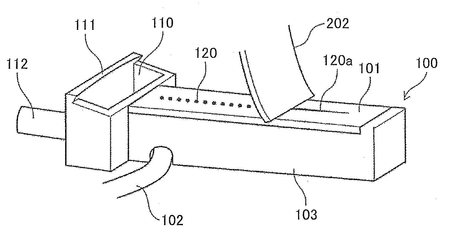
[0119]In the present embodiment, regarding the configuration the curve of the scraper 111b in the downstream of the moving direction (the wiping direction) of the wiper 202 is milder than the curve of the scraper 111a in the upstream (the curvature is smaller). In other words, the curvature radius of the contact surface of the scraper 111b in the downstream is bigger than the curvature radius of the contact surface of the scraper 111a in the upstream.

[0120]Being configured in such a way as described above, after waste ink adhered to the wiper 202 is scraped off with the scraper 111a of the wiper cleaner 111 in the upstream of the moving direction first, the waste ink is scraped off with the scraper 111a of the wiper cleaner 111 in the downstream of the moving direction.

[0121]Here, the curve of the scraper 111b of the wiper cleaner 111 in the downstream of the moving direction of the wiper 202 is milder than the curve of the scraper 111a of the wiper cleaner 111 in the upstream.

[012...

fourth embodiment

[0126]In the present embodiment, regarding the configuration the wiper cleaner 111 has a sloping surface 111c and a sloping surface 111d respectively on the other side of the scraper 111a and the scraper 111b (in the downstream of the moving direction of the wipers), which incline in such an angle as the contact pressure of the wiper 202 gradually decreases.

[0127]This prevents the wiper 202 from immediately getting away from the wiper cleaner 111 after waste ink adhered to the wiper 202 is scraped off by the scraper 111a and the scraper 111b of the wiper cleaner 111.

[0128]That is to say, waste ink may remain on the wiper 202 even after the wiper cleaner 111 cleans the wiper 202. In this case, if the wiper 202 immediately recovers from the curved state to the original state, the remaining waste ink may be scattered.

[0129]Here, the sloping surface 111c and the sloping surface 111d are provided respectively in the downstream of the scraper 111a and the scraper 111b, so that the curvin...


PUM


Abstract

A liquid ejector includes a head having a plurality of nozzles arranged along a first direction of a nozzle surface of the head to eject a droplet from the nozzles, and an ejection detector to detect whether or not a droplet is ejected from the plurality of nozzles of the head by detecting an electrical change generated when the droplet lands onto the ejection detector. The ejection detector includes a droplet landing surface arranged opposed to the nozzle surface, a wiper to wipe the droplet off the droplet landing surface along the first direction, and a cleaner having a contact surface to remove the droplet adhered to the wiper after the wiper wipes the droplet landing surface. The contact surface has a curvature such that side ends of the wiper contacts with the contact surface at first, and then a center part of the wiper contacts the contact surface.

Description

CROSS-REFERENCE TO RELATED APPLICATIONS[0001]The present application is a continuation application of International Application No. PCT / JP2015 / 054226, filed Feb. 17, 2015, which claims priority to Japanese Patent Application No. 2014-033299, filed Feb. 24, 2014. The contents of these applications are incorporated herein by reference in their entirety.BACKGROUND OF THE INVENTION[0002]1. Field of the Invention[0003]The embodiments of the present disclosure relate to liquid ejectors and liquid ejecting detectors.[0004]2. Description of the Related Art[0005]An inkjet recording apparatus, for example, which ejects ink droplets from a recording head to form an image, is known as a liquid ejector for a printer, a facsimile machine, a copier, a plotter, a multifunction peripheral, etc.[0006]Such an inkjet recording apparatus may be provided with a liquid ejecting detector which detects a condition of ejection of ink droplets from the recording head. In a case that a nozzle performing abnorm...

Claims


Application Information

Patent Timeline
Patent Type & Authority Applications(United States)
IPC IPC(8): B41J2/165
CPCB41J2/16538B41J2/16541B41J2/16579B41J2/01
Inventor MASAOKA, SHINGOTAKEUCHI, SHOTAROHISADA, MASAHIKOTAKAHASHI, KENTA
Owner RICOH KK
Why Eureka
Try Eureka