Rotor arrangement for a turbomachine and compressor

a technology of rotor spool and turbomachine, which is applied in the direction of liquid fuel engines, air transportation, climate sustainability, etc., can solve the problems of affecting the performance of the engine, the smell of oil, and the disadvantages of such oil accumulation, so as to reduce the cost of production and maintenance, reduce the effect of fuel consumption and compact structure shap

Active Publication Date: 2016-11-10
MTU AERO ENGINES GMBH
View PDF6 Cites 7 Cited by
  • Summary
  • Abstract
  • Description
  • Claims
  • Application Information

AI Technical Summary

Benefits of technology

The present invention proposes a rotor arrangement for a turbomachine that prevents fluid accumulations, especially oil accumulations. The invention also includes a balancing device on the hub for balancing the rotor stages, which can partially or completely replace separate balancing of the rotor stages. This balancing can reduce or eliminate oil accumulations in the rotor spool, which can cause damage and lead to contamination or fire. The invention optimizes the structural space and weight of the rotor spool, resulting in economic advantages. Additionally, the invention allows for balancing directly on the hub, reducing balancing time and expenditure overall.

Problems solved by technology

For example, after the rotor starts up again, oil can be distributed as a liquid into regions of the turbomachine that bring about considerable disadvantages for such oil accumulation.
In one possible use of the turbomachine as an aircraft engine, the oil can enter into the cabin air via ducts in the casing when the rotors start up again and this leads to the smell of oil and contaminations therein.

Method used


Image

  • Rotor arrangement for a turbomachine and compressor
  • Rotor arrangement for a turbomachine and compressor

Examples


Embodiment Construction

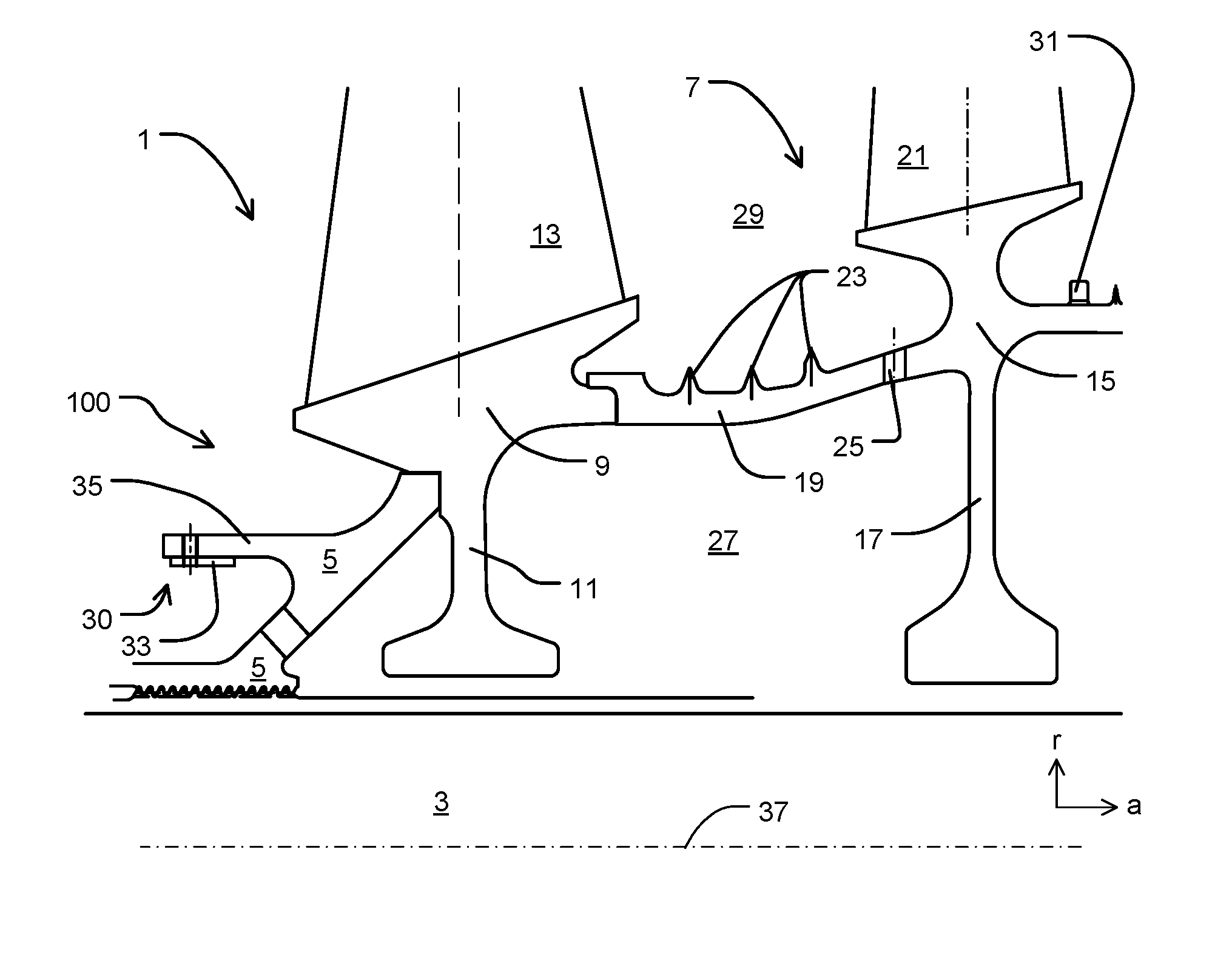
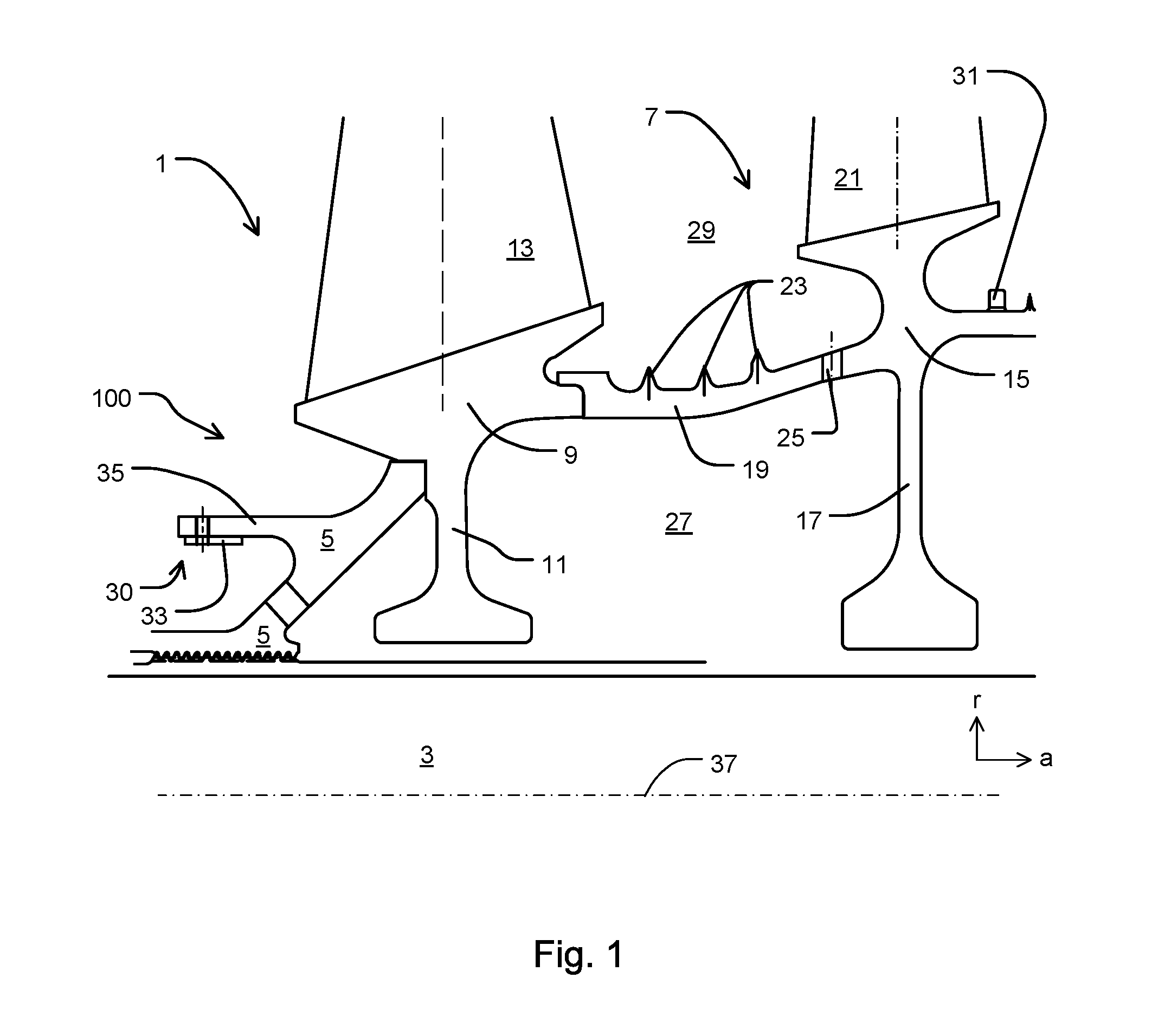
[0033]FIG. 1 shows a rotor arrangement 100 according to the invention having a first rotor stage 1, a shaft 3, and a hub 5, as well as a second rotor stage 7. The direction of through-flow of the rotor corresponds to the axial direction a. Additional coordinate axes are the radial direction r and the peripheral direction u.

[0034]The first rotor stage 1 comprises a first basic rotor body 9 having a radially inwardly directed first rotor disk 11 and an integrally joined first blade 13. The first basic rotor body 9 is joined upstream (left in FIG. 1) in form-fitting manner to the hub 5 and downstream (right in FIG. 1) in form-fitting manner to the second rotor stage 7.

[0035]The second rotor stage 7 comprises a second basic rotor body 15 with a radially inwardly directed second rotor disk 17, a spool-shaped rotor arm 19 and an integrally joined second blade 21. The second basic rotor body 15 is joined upstream in form-fitting manner to the first basic rotor body 9 by means of the rotor ...


PUM


Abstract

The present invention relates to a rotor arrangement (100) for a turbomachine, having a rotor with a first rotor stage (1), a shaft (3), and a first hub (5) for joining the first rotor stage (1) to the shaft (3). The first hub (5) has a balancing device (30) for balancing the first rotor stage (1). In addition, the present invention relates to a compressor.

Description

BACKGROUND OF THE INVENTION[0001]The present invention relates to a rotor arrangement for a turbomachine and compressor claimed herein.[0002]In rotors for turbomachines, in specific situations during operation, accumulations of liquids are formed in cavities of rotor spools due to centrifugal force during the operation of rotors. This accumulated liquid can flow into another region of the rotors only when the rotors are shut down and may cause various disadvantages. For example, after the rotor starts up again, oil can be distributed as a liquid into regions of the turbomachine that bring about considerable disadvantages for such oil accumulation. In one possible use of the turbomachine as an aircraft engine, the oil can enter into the cabin air via ducts in the casing when the rotors start up again and this leads to the smell of oil and contaminations therein.SUMMARY OF THE INVENTION[0003]An object of the present invention is to propose a rotor arrangement for a turbomachine, in wh...

Claims


Application Information

Patent Timeline
Patent Type & Authority Applications(United States)
IPC IPC(8): F01D5/02F01D25/00F04D29/32F01D5/06F01D5/34F04D29/70
CPCF01D5/027F01D5/34F04D29/701F04D29/321F05D2240/60F01D25/002F05D2220/32F05D2240/24F01D5/06F05D2220/3219Y02T50/60
Inventor BOEWING, STEFAN
Owner MTU AERO ENGINES GMBH
Why Eureka
Try Eureka