Liner for a gas turbine engine

Active Publication Date: 2016-11-10
RAYTHEON TECH CORP
View PDF5 Cites 7 Cited by
  • Summary
  • Abstract
  • Description
  • Claims
  • Application Information

AI Technical Summary

Benefits of technology

[0004]In one aspect, a gas turbine engine is provided having a fan case and a translating sleeve positioned downstream from the fan case. A flow channel extends between the fan case and the translating sleeve. The flow channel includes an inner diameter and an outer diameter.

Problems solved by technology

Reducing vibratory stresses to meet the Goodman capability is technically challenging and is typically accomplished by making changes

Method used


Image

  • Liner for a gas turbine engine
  • Liner for a gas turbine engine
  • Liner for a gas turbine engine

Examples


case 3

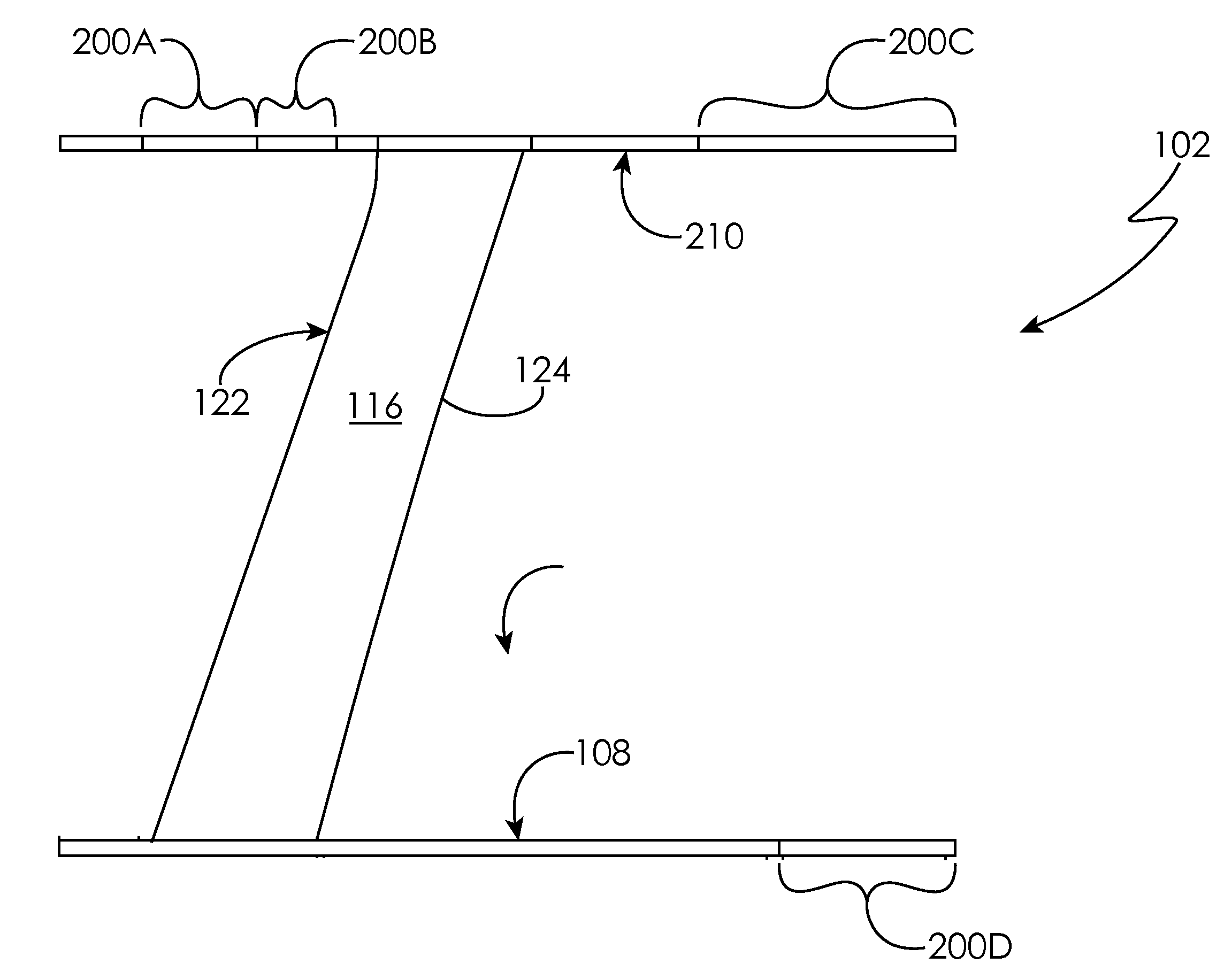
[0043, illustrated in FIG. 3, includes patches of liner 200 along the wall of the flow channel 102. The patches include individual segments of liner 200 that are utilized to cover a portion of the wall of the flow channel 102. Each patch is independent of every other patch, although some patches may abut one another. Two patches 200A and 200B are on the outer diameter 210, wherein patches 200A and 200B are forward of the vane leading edge 122. Another patch 200C is aft of the vane trailing edge 124. Another patch 200D is on the inner diameter 108 and is aft of the vane trailing edge 124. The following table summarizes the impedance values used in Cases 2 and 3.

Patch 200APatch 200BPatch 200CPatch 200DCaseResistanceReactanceResistanceReactanceResistanceReactanceResistanceReactance21.5702−3.01421.5329−8.15681.2094−3.25300.94942.392830.4000−0.60000.4000−0.60000.5700−0.25000.5700−0.2500

[0044]The following table gives a summary of the predicted vibratory stress for these three cases. The ...


PUM


Abstract

A gas turbine engine is provided having a fan case and a translating sleeve positioned downstream from the fan case. A flow channel extends between the fan case and the translating sleeve. The flow channel includes an inner diameter and an outer diameter. A structural guide vane is positioned within the flow channel and extends from the inner diameter to the outer diameter. A liner is positioned between an aft end of the fan case and an aft end of the translating sleeve to reduce vibratory stress on the structural guide vane.

Description

TECHNICAL FIELD OF THE DISCLOSED EMBODIMENTS[0001]The embodiments herein generally relate to gas turbine engines and, more particularly, to a liner for a gas turbine engine.BACKGROUND OF THE DISCLOSED EMBODIMENTS[0002]Generally, a vibratory stress allowance of the structural guide vane is limited to a percentage of the structural guide vane's Goodman capability, wherein the Goodman capability is a maximum amount of vibratory stress that the structural guide vane can withstand before cracking. Reducing vibratory stresses to meet the Goodman capability is technically challenging and is typically accomplished by making changes to the airfoil part, the airfoil material properties, the steady stress of the airfoil, or by modifying the source of the vibration.[0003]Liners are currently used in the engine or the nacelle of the engine to reduce the fan module noise. As such the liner is designed to reduce noise. Particularly, the liner is designed to attenuate frequencies over 1,000 Hertz.S...

Claims


Application Information

Patent Timeline
IPC IPC(8): F04D29/66F04D29/52F02K3/06F04D29/54
CPCF04D29/668F04D29/541F04D29/526F05D2240/12F05D2220/36F05D2260/96F02K3/06F01D25/04F02K1/08F02K1/827F02C7/045F01D25/162F05D2260/963F05D2250/283
Inventor LOGUE, MICHAELA M.ATASSI, OLIVER V.
Owner RAYTHEON TECH CORP
Why Eureka
Try Eureka