LED tube for retrofitting in a fluorescent tube lighting fixture

a technology for fluorescent tubes and led tubes, which is applied in the direction of lighting safety devices, semiconductor devices of light sources, lighting and heating apparatus, etc., can solve the problems of not meeting the electric safety requirement, the user cannot touch any parts at the mains voltage, and the risk of an electric shock during the mounting step of led tubes, etc., to achieve a simple and inexpensive solution to the risk of an electric shock

Inactive Publication Date: 2016-11-10
SIGNIFY HLDG BV
View PDF9 Cites 7 Cited by
  • Summary
  • Abstract
  • Description
  • Claims
  • Application Information

AI Technical Summary

Benefits of technology

[0007]It is an object of the present invention to overcome this problem, and to provide a simple and inexpens...

Problems solved by technology

When retrofitting a fluorescent tube with a LED tube a problem related to the risk of an electric shock during the mounting step of the LED tube occurs.
According to the safety regulations in the field of electricity, fluorescent tube lighting fixtures are to be constructed in such a way that, when a fluorescent tube is replaced, it is not possible for a user to touch any parts at the mains voltage even if the fluorescent tube lighting fixture were carrying voltage.
With LED tubes, this electric safety requirement is not necessarily met.
Therefore, in a practical situation, when the LED tube is being mounted on a fluorescent tube lighting fixture, the contact pins at one end of the LED ...

Method used


Image

  • LED tube for retrofitting in a fluorescent tube lighting fixture
  • LED tube for retrofitting in a fluorescent tube lighting fixture
  • LED tube for retrofitting in a fluorescent tube lighting fixture

Examples


Embodiment Construction

[0034]The present invention will now be described more fully hereinafter with reference to the accompanying drawings, in which currently preferred embodiments of the invention are shown. This invention may, however, be embodied in many different forms and should not be construed as limited to the embodiments set forth herein; rather, these embodiments are provided for thoroughness and completeness, and fully convey the scope of the invention to the skilled person.

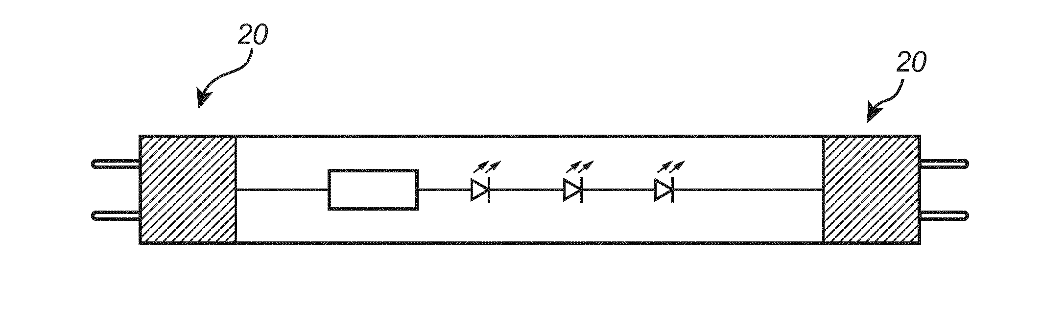
[0035]This invention is compatible with all fluorescent tube lighting fixture having a preheat phase. During the preheat phase the fluorescent tube lighting fixture is arranged to apply a current between a first pair of contact pins at a first end of the fluorescent tube and between a second pair of contact pins at a second end of the fluorescent tube. The current is applied in order to heat a corresponding filament connected between said first and second pair of contact pins, respectively.

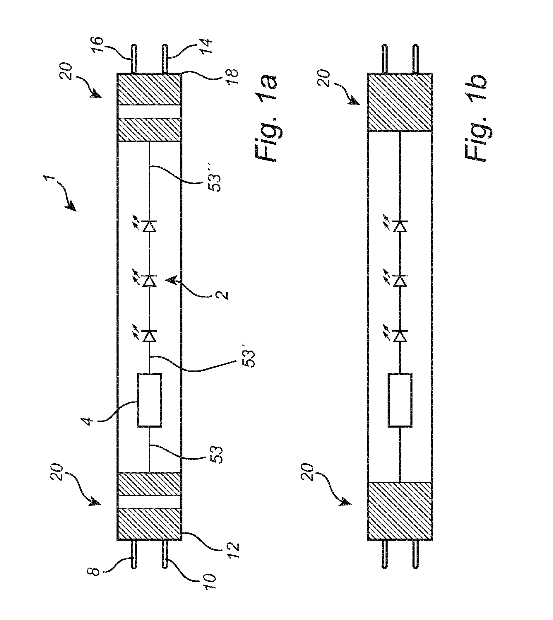
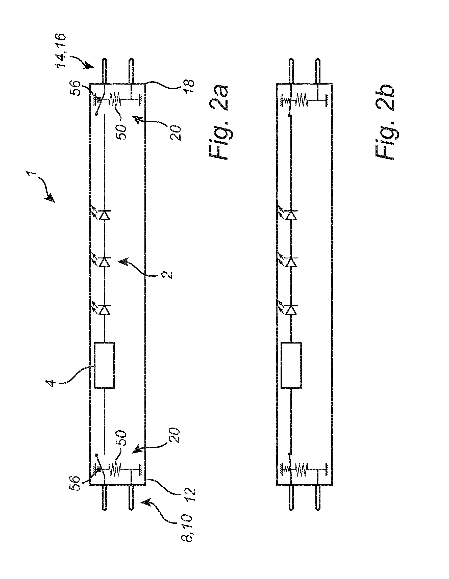
[0036]In FIGS. 1a and 1b, an examp...


PUM


Abstract

The present invention relates to a LED tube (1) for retrofitting in a fluorescent tube lighting fixture having a preheat phase during which the fluorescent tube lighting fixture is arranged to preheat filaments of a fluorescent tube, the LED tube (1) comprising: an array of LEDs (2), a LED driver (4) for driving the array of LEDs (2), a first pair of contact pins (8, 0) at a first end (12) of the LED tube (1) and a second pair of contact pins (14, 16) at a second end (18) of the LED tube (1) for connecting the LED tube (1) electronically and mechanically to the fluorescent tube lighting fixture, the first pair of contact pins (8, 10) being connected forming a first circuitry, the second pair of contact pins (14, 16) being connected forming a second circuitry, the LED driver (4) being connected between the first circuitry and the second circuitry, and a temperature controlled switch (20) having an open state and a closed state, and being arranged to adapt the closed state when heated, such that a current path between the first circuitry and the second circuitry is obtained, wherein a preheat current passing between the first pair of contact pins (8, 10) during the preheat phase of the fluorescent tube lighting fixture is arranged to heat the temperature controlled switch.

Description

FIELD OF THE INVENTION[0001]The present invention is related to a LED tube for retrofitting in a fluorescent tube lighting fixture.BACKGROUND OF THE INVENTION[0002]In a traditional fluorescent tube lamp, the body of the lamp is a straight tube with a length of 15 to 60 times the diameter of the tube. Fluorescent tubes are low-pressure mercury discharge lamps in which the inner surface of the tube is coated with fluorescent material. The fluorescent tube lamp consists of an air-tight glass tube containing a small amount of mercury, an inert gas, a fluorescent coating, such as phosphor, and electrodes. At each end of the fluorescent tube, there is a lid with two symmetrically positioned contact pins, to which the electrodes are connected. Power supply to the fluorescent tube is provided via these contact pins. When the lamp is in operation, the temperature of the electrodes must be sufficiently high, so that electrons release from them. A fluorescent lamp does not ignite at a normal o...

Claims


Application Information

Patent Timeline
IPC IPC(8): F21K9/278F21V15/015F21V23/00F21K9/272F21V23/04
CPCF21K9/278F21K9/272F21V23/0457F21Y2103/10F21V15/015F21Y2115/10F21V23/003F21V25/04Y02B20/30H05B41/2981
Inventor GIELEN, VINCENT STEFAN DAVIDVERHOEVEN, MARK
Owner SIGNIFY HLDG BV
Why Eureka
Try Eureka