Corner seal device for ductwork for conditioned air and method of assembly of such ductwork to prevent air leaks

a technology of conditioned air and sealing device, which is applied in the direction of ducting arrangement, lighting and heating apparatus, heating types, etc., can solve the problems of a relatively significant delay in the production schedule of ductwork sections, the system of assembling flanged ductwork, etc., and achieve the effect of preventing known potential air leakag

Active Publication Date: 2016-11-10
CAPITAL HARDWARE SUPPLY LLC
View PDF5 Cites 1 Cited by
  • Summary
  • Abstract
  • Description
  • Claims
  • Application Information

AI Technical Summary

Benefits of technology

[0016]The present invention relates to a corner seal device for ductwork for conditioned air, and a method of assembly of such ductwork in which known potent

Problems solved by technology

Disadvantages of the Current System of Assembling Flanged Ductwork Sections
One disadvantage of the present system of assembling such flanged ductwork sections relates to the presence of a notch between the edges of adjacent flanges, and an aperture in eac

Method used


Image

  • Corner seal device for ductwork for conditioned air and method of assembly of such ductwork to prevent air leaks
  • Corner seal device for ductwork for conditioned air and method of assembly of such ductwork to prevent air leaks
  • Corner seal device for ductwork for conditioned air and method of assembly of such ductwork to prevent air leaks

Examples


Embodiment Construction

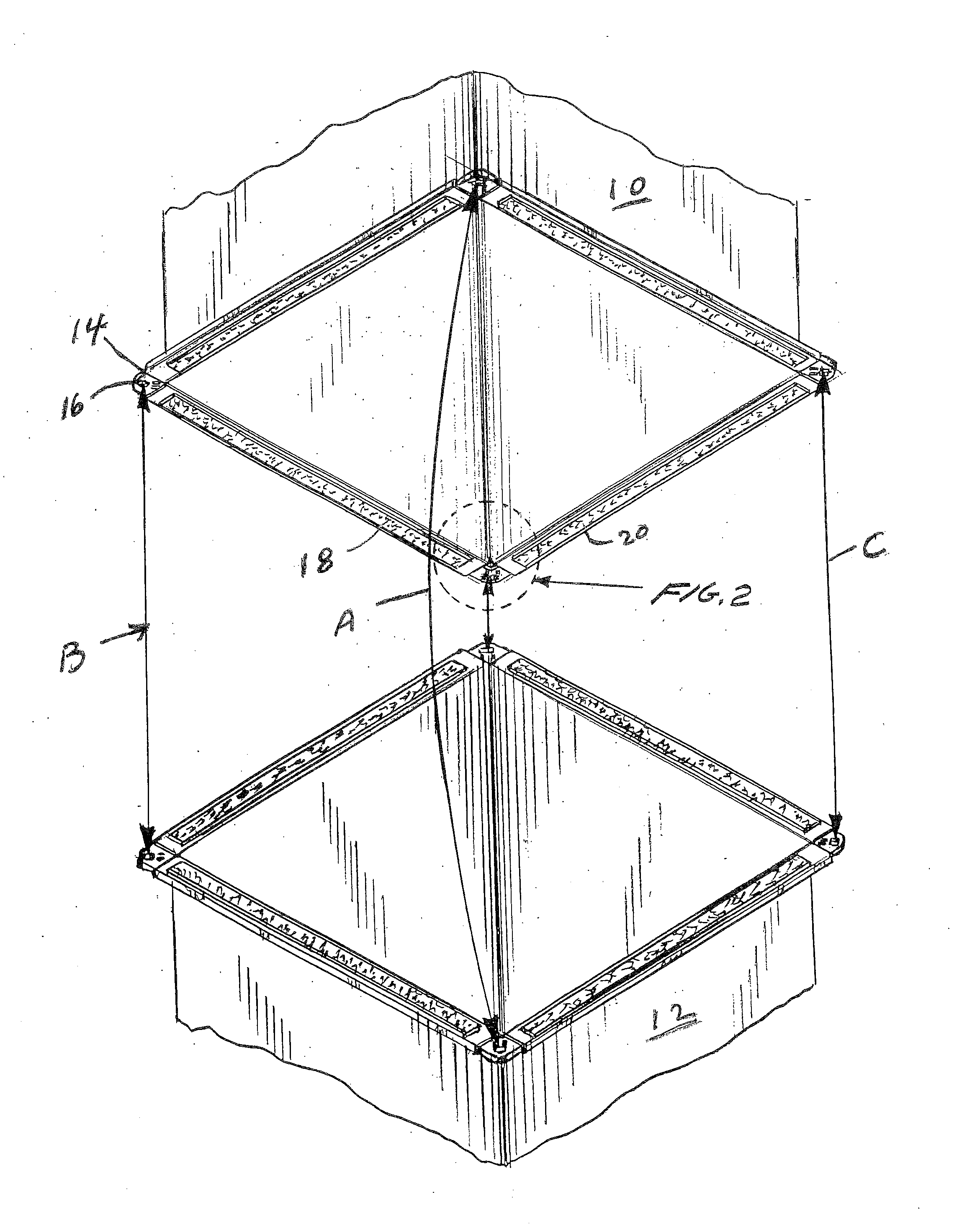
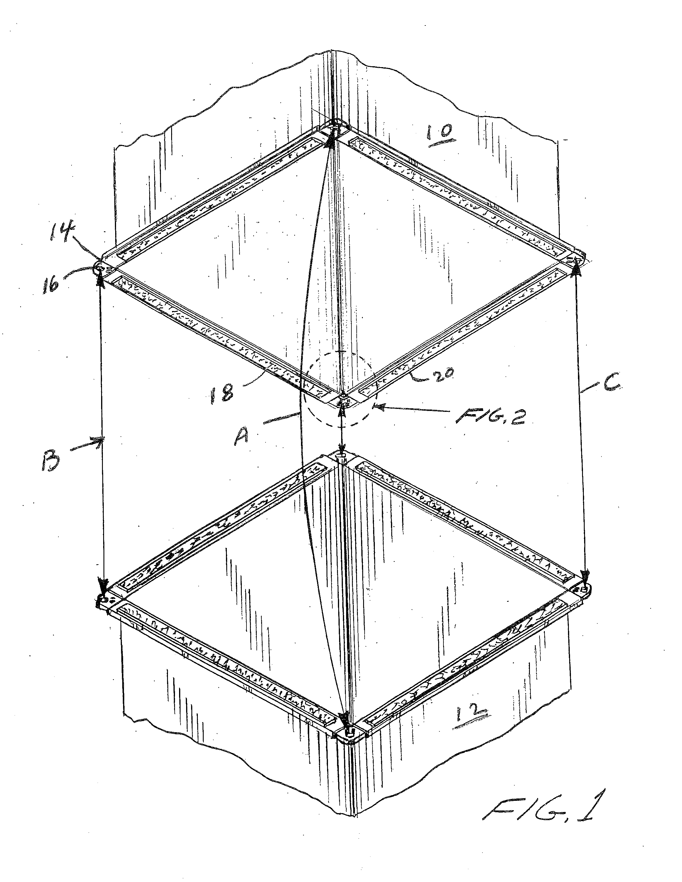
[0053]In the description which follows, reference is sometimes made to a corner structure of a conditioned air duct. Such descriptions are illustrative of a typical corner of the ductwork. Each such section of ductwork which has a rectangular section generally has four of such corner structures. The expression “rectangular” duct section is also meant to contemplate such duct sections having a square cross-section.

[0054]Referring initially to FIG. 1, there is shown a pair of flanged ductwork sections 10,12 positioned for attachment in end-to-end relation as shown by the arrows A, B, and C, with suitable fasteners according to known practice. The faces of each such section of ductwork are to be attached in face-to-face relation. In general, the ductwork sections are attached to each other by positioning the ends in face-to-face relation and by passing a bolt through apertures 16 of the known corner mounting angle plates 14 similar to the angle plates disclosed in U.S. Pat. Nos. 5,283,...


PUM


Abstract

A corner seal device is disclosed for use in preventing unwanted air leaks in ductwork sections intended for directing conditioned air in heating, ventilating and air conditioning systems (i.e., HVAC systems). The corner seal device eliminates potential air leaks caused inter alia, by the flange members of the ductwork sections, and further, it avoids previously known costly expenses and loss of time to seal the unwanted air leaks created when the flange members of the ductwork sections are made and are prepared for assembly of the ductwork sections. A method of assembly of such ductwork sections incorporating the unique corner seal device of the invention, is also disclosed. A duct for directing conditioned air in heating, ventilating and air conditioning systems incorporating such ducts is also disclosed. A heating, ventilating and air conditioning system incorporating such unique corner seal device and related structures is also disclosed.

Description

CROSS-REFERENCE TO RELATED APPLICATIONS[0001]This application claims priority to U.S. provisional application No. 61 / 915,348, filed Dec. 12, 2013, the disclosure of which is incorporated in its entirety by reference herein, and made a part of this application.BACKGROUND OF THE INVENTION[0002]1. Field of the Invention[0003]The present invention relates to the assembly of ductwork sections having channel flanges at their ends. More particularly, the invention relates to a method of assembly of such flanged ductwork sections utilizing a unique sealing bracket which quickly and efficiently seals the assembled ductwork sections such that air leaks are prevented.[0004]2. Description of the Related Art[0005]Presently, flanged ductwork sections which are formed with such channel flanges, are assembled by the placement of angle plates into the corners defined by the channel flanges positioned at the ends of the ductwork sections, as more particularly described in U.S. Pat. Nos. 5,283,944, 5,...

Claims


Application Information

Patent Timeline
IPC IPC(8): F24F13/02F16L23/16F16L23/14
CPCF24F13/0209F24F13/0245F16L23/16F16L23/14F16J15/104
Inventor YOSKOWITZ, DAVID
Owner CAPITAL HARDWARE SUPPLY LLC
Why Eureka
Try Eureka