Method, program, and device for manufacturing progressive refractive power lens, manufacturing method for progressive refractive power lens, and lens supply system

a manufacturing method and lens technology, applied in the field of lens supply system, can solve the problems of unintended aberration, unsatisfactory vision of expected wearer, and problem of vision through spectacle lens, and achieve the effect of reducing the dissatisfaction of expected wearer

Inactive Publication Date: 2016-11-10
HOYA LENS THAILAND LTD
View PDF7 Cites 7 Cited by
  • Summary
  • Abstract
  • Description
  • Claims
  • Application Information

AI Technical Summary

Benefits of technology

[0006]Here, how the person perceives a blurred image and a sharpened image (blur sensitivity indicating sensitivity relative to blur) is different from person to person. Specifically, the blur sensitivity is different depending on the size of the pupil diameter, transparency of an ocular media in an eyeball, an ability to form a perceived image in the brain. As a result of intensive studies, the inventor obtains knowledge such that after the blur sensitivity caused by the prescription power determined by the optometric work is obtained, the spectacle lens which can reduce the dissatisfaction can be selected and designed based on the obtained blur sensitivity.
[0008]According to the present embodiment, since the basic design lens of which the area of the clear-visible region of the first refractive unit is appropriately adjusted according to the blur sensitivity different for each person is selected as the design reference lens of the progressive lens to be worn by the spectacles wearer, the progressive lens which can reduce the dissatisfaction can be designed.
[0021]According to the present embodiment, a method, a program, and a device for manufacturing a progressive lens, a manufacturing method for the progressive lens, and a lens supply system which are suitable for reducing dissatisfaction of an expected wearer relative to a vision through the progressive lens are provided.

Problems solved by technology

Especially, when the type, in which the refractive power changes in the lens, such as the progressive lens is used, the inconsistency between the prescription power and the full corrected value may cause a problem in the vision through the spectacle lens.
Therefore, when the prescription power is deviated from the full corrected value, unintended aberration is generated.
Therefore, for example, when the expected wearer wears the spectacle lens created with the prescription power apart from the full corrected value, the expected wearer may feel unsatisfied about the vision.

Method used


Image

  • Method, program, and device for manufacturing progressive refractive power lens, manufacturing method for progressive refractive power lens, and lens supply system
  • Method, program, and device for manufacturing progressive refractive power lens, manufacturing method for progressive refractive power lens, and lens supply system
  • Method, program, and device for manufacturing progressive refractive power lens, manufacturing method for progressive refractive power lens, and lens supply system

Examples


case 1

[0096] Visual Acuity Level of Expected Wearer Through Distance Portion is High and Distance Prescription Power is Full Corrected Value or Value Approximating to it

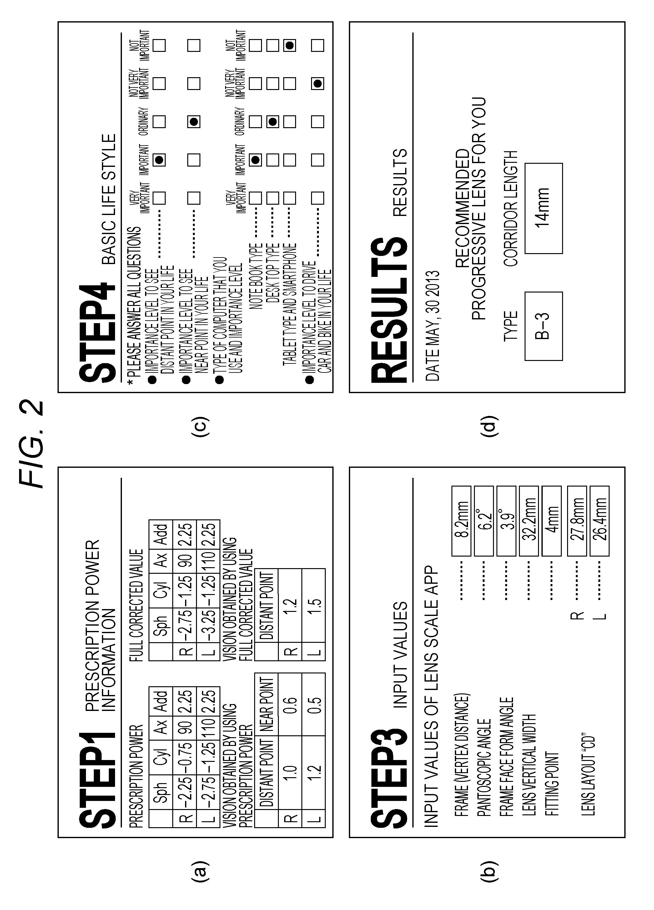
[0097]Since a distance prescription power is the full corrected value or a value approximating to it, the blur in the image of the object when the person looks at the distant point is small. The relation (difference) between the distance prescription power and the full corrected value is obtained based on the prescription power and the full corrected value input via the screen in FIG. 2A. Therefore, even when the design type of the distance portion is slightly changed, the blur is hardly perceived at least when the person looks at the distant point. Therefore, in case 1, it is estimated that the expected wearer is dull relative to the blur when using the distance prescription power and has low blur sensitivity. In addition, it is estimated that the blur sensitivity gets lower as the distance prescription power and the full...

case 2

[0103] Visual Acuity Level of Expected Wearer Through Distance Portion is High and Distance Prescription Power is Adjusted to Positive Power from Full Corrected Value

[0104]Since the distance prescription power is adjusted to a value apart from the full corrected value to the positive power side, the blur is slightly larger when the person looks at the distant point. Especially, the blur generated when the person looks at the object through the peripheral region of the distance portion is large. Therefore, for example, when the design type of the distance portion is changed to the further positive power side, there is a possibility that the blur at the time of looking at the distant point increases. Therefore, incase 2, it is estimated that the expected wearer is sensitive relative to the blur when using the distance prescription power and has high blur sensitivity. In addition, it is estimated that the blur sensitivity gets higher as the distance prescription power and the full corr...

case 3

[0107] Visual Acuity Level of Expected Wearer Through Distance Portion is not High and Distance Prescription Power is Full Corrected Value or Value Approximating to it

[0108]In case 3, similarly to case 1, since the distance prescription power is the full corrected value or the value approximating to it, it is estimated that the expected wearer has low blur sensitivity. In case 3, the eighth basic design point DES8 is calculated by using the following formula to consider a case where it is determined that the vision level is not high.

DES8=ΔPW×10

[0109]In case 3, the shift to the distance soft side can be performed similarly to case 1. However, since the visual acuity level of the expected wearer through the distance portion is not high, the shift of the range of the basic design lens is not recommended. Therefore, as illustrated in FIG. 6C, the range of the selected basic design lens is not shifted to the distance soft side.


PUM


Abstract

A method includes a blur sensitivity estimating step indicating a sensitivity of a spectacles wearer relative to a blur at the time when the spectacles wearer looks at an object through lenses having a prescription power of a first refractive unit, a first area adjusting step for adjusting an area of the first refractive unit based on the estimated blur sensitivity, a design reference lens selecting step for selecting at least a single basic design lens for coinciding with or approximating to the lens of which the area of the first refractive unit is adjusted in the first area adjusting step from among a predetermined basic design lens group as a design reference lens of the progressive lens to be worn by the wearer, and a data creating step for creating data to manufacture the progressive lens based on a lens design of the selected design reference lens.

Description

TECHNICAL FIELD[0001]The present invention relates to a method, a program, and a device for manufacturing a progressive refractive power lens (referred to as “progressive lens” below), a manufacturing method for the progressive lens, and a lens supply system.BACKGROUND ART[0002]When spectacles are created at a spectacles store, to improve vision of a wearer at the time when the wearer wears the spectacles, a prescription power of the wearer is measured (for example, JP 2002-200041 A).[0003]For example, an inspector who performs prescription measurement measures a temporary prescription power by using a device for objectively measuring a refraction power of an eye such as an autorefractometer. Subsequently, the inspector selects an trial lens in reference to the measuring result (temporary prescription power) and arranges the trial lens in front of the eye of the expected wearer by using a phoropter or a test frame and makes the expected wearer visually recognize a optotype (visual t...

Claims


Application Information

Patent Timeline
Patent Type & Authority Applications(United States)
IPC IPC(8): G02C7/02A61B3/00G02C13/00G02C7/06
CPCG02C7/027G02C13/005A61B3/0025G02C7/066
Inventor HATANAKA, TAKASHI
Owner HOYA LENS THAILAND LTD
Why Eureka
Try Eureka