
Electric Power Conversion Device and Method for Charging and Discharging Energy Storage Devices

Active Publication Date: 2016-11-17
HUETTINGER ELECTRONICS GMBH & CO KG
View PDF2 Cites 3 Cited by
  • Summary
  • Abstract
  • Description
  • Claims
  • Application Information

AI Technical Summary

Benefits of technology

The current converter device can increase its efficiency by controlling the power flow direction of the voltage converter, which allows better tapping or provision of power. It is effective in absorbing fast current or voltage peaks in the power grid. The device can transfer energy between energy stores and other current converter devices, improving overall energy efficiency.

Problems solved by technology

The problem with alternative energies, e.g., solar or wind power, is that it is not possible to manipulate the times during which energy is generated and surplus energy has to be temporarily stored in order to be available at times when no energy can be generated.

Method used


Image

  • Electric Power Conversion Device and Method for Charging and Discharging Energy Storage Devices
  • Electric Power Conversion Device and Method for Charging and Discharging Energy Storage Devices
  • Electric Power Conversion Device and Method for Charging and Discharging Energy Storage Devices

Examples


Embodiment Construction

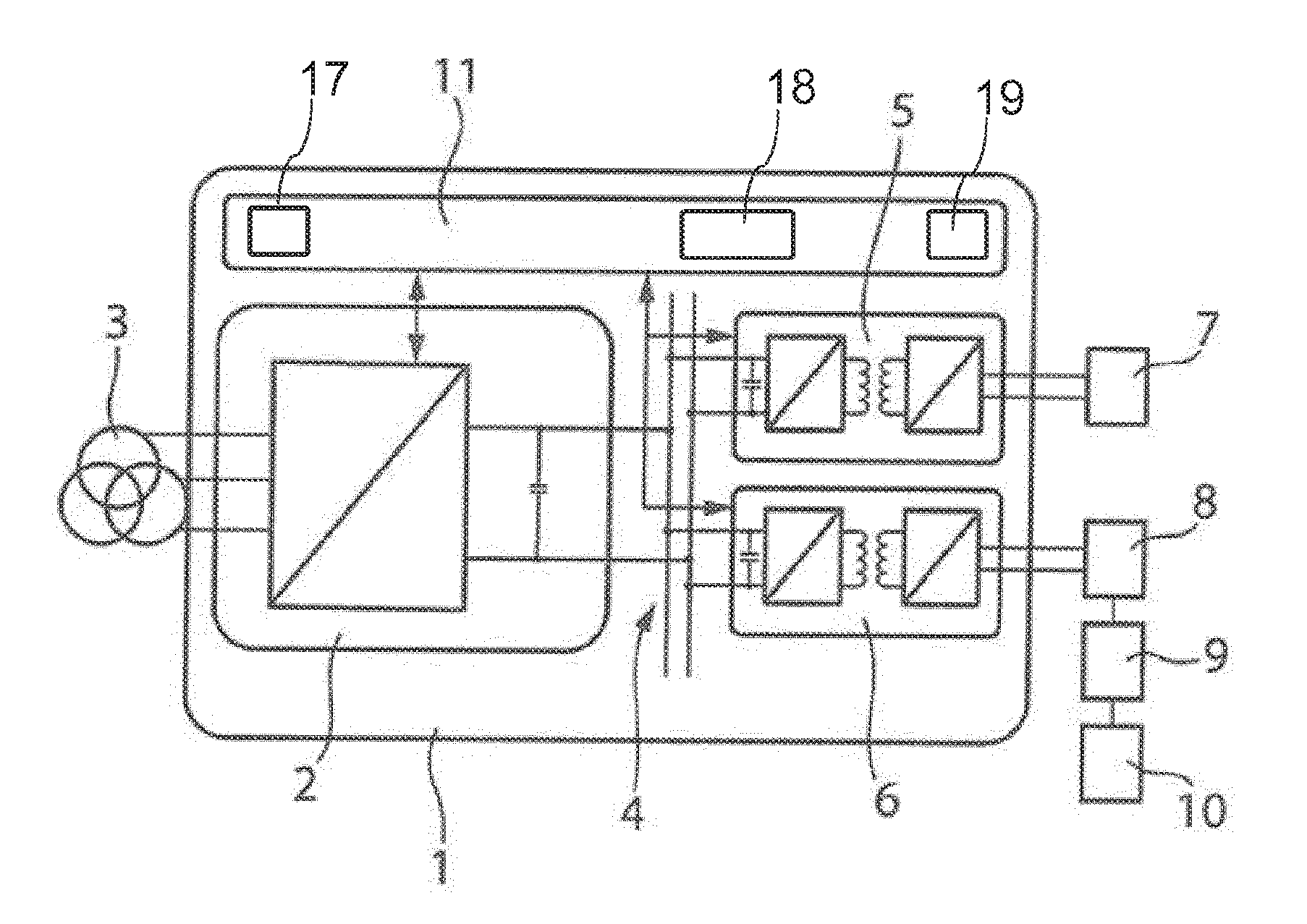
[0082]FIG. 1 shows a current converter device 1 comprising a first voltage converter 2 that can be connected to a single-phase or multiphase power grid 3. The first voltage converter 2 can be formed as an AC / DC converter, in particular a bidirectional AC / DC converter, and is connected to an intermediate circuit 4, to which a second and a third voltage converter 5, 6 are connected in turn. The voltage converters 5, 6 may be formed as DC / DC converters, in particular bidirectional DC / DC converters, for example, and can each convert over 5 kW of power. More than the two voltage converters 5, 6 shown can be connected to the intermediate circuit 4. The voltage converters 5, 6 can each be connected to one or more electrochemical energy converters 7 to 10, the voltage converter 5 being connected to the electrochemical energy converter 7 and the voltage converter 6 being connected to the electrochemical energy converters 8 to 10 in the embodiment shown. The electrochemical energy converters ...


PUM


Abstract

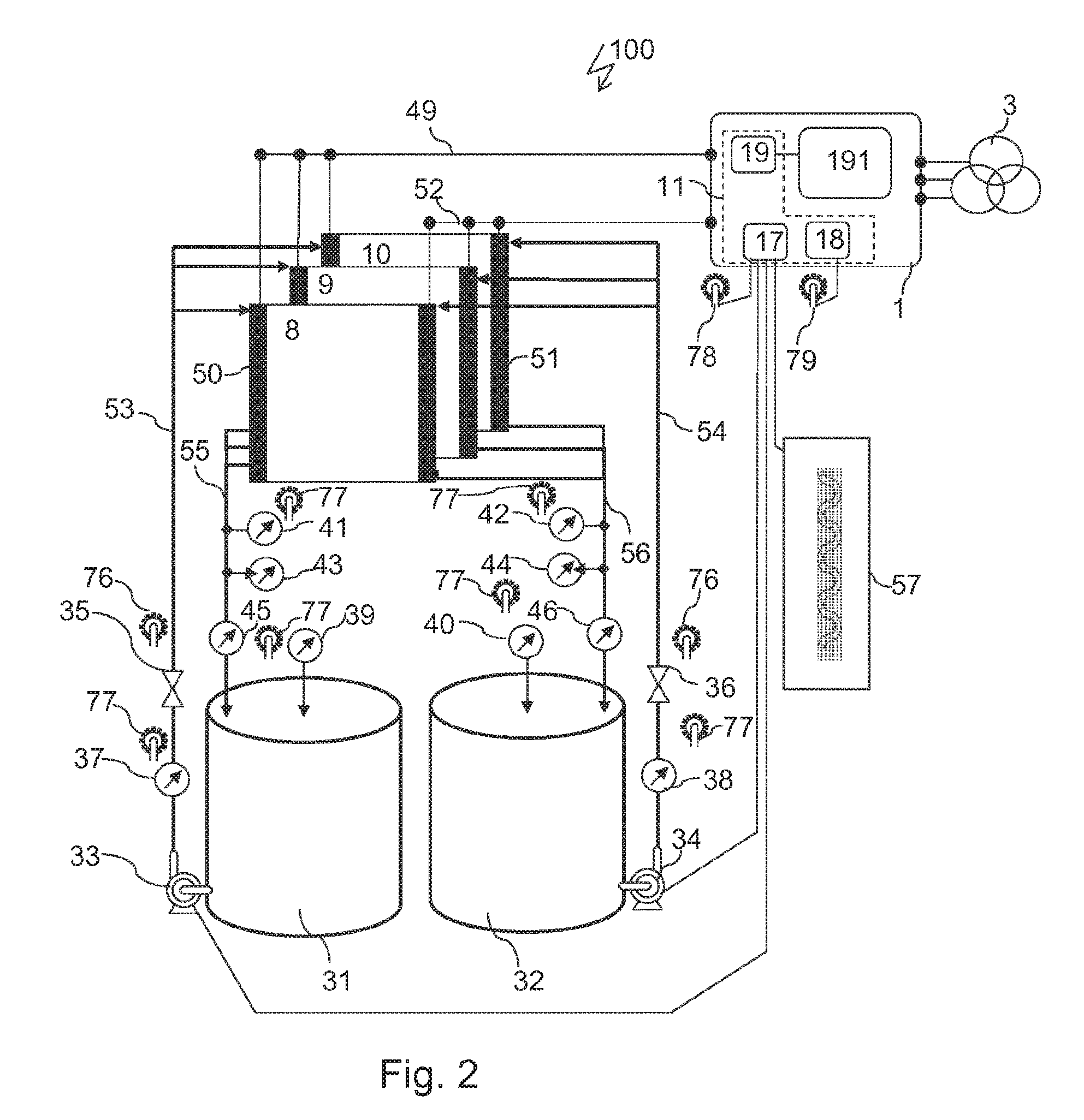
An electric power conversion device for charging and discharging energy storage devices having at least one bidirectional voltage converter which can be connected to a power supply network and to at least one electrochemical energy converter for an energy storage device that is configured as a flow battery and has a circulation arrangement for electrolytes. The electric power conversion device has a controller connected to the voltage converter and is designed to control the voltage converter with regard to the power flow direction thereof. The controller is designed to control one or more energy storage peripheral devices associated with the electrolytes depending on the power flow direction of the voltage converter specified by the controller. The controller has at least one control port for connection of at least one of these energy storage peripheral devices.

Description

CROSS-REFERENCE TO RELATED APPLICATIONS[0001]This application is a continuation of and claims priority under 35 U.S.C. §120 to PCT Application No. PCT / EP2015 / 051586 filed on Jan. 27, 2015, which claims priority to German Application No. DE 10 2014 100 989.4, filed on Jan. 28, 2014. The contents of both of these priority applications are hereby incorporated by reference in their entireties.TECHNICAL FIELD[0002]The invention relates to current converter devices and methods for charging and discharging energy stores.BACKGROUND[0003]Alternative energies are becoming ever more important. The problem with alternative energies, e.g., solar or wind power, is that it is not possible to manipulate the times during which energy is generated and surplus energy has to be temporarily stored in order to be available at times when no energy can be generated. It is therefore necessary to use energy storage systems. However, energy storage systems are subject to losses, which should be avoided.[0004]...

Claims


Application Information

Patent Timeline
IPC IPC(8): H02J7/00H02M3/24
CPCH02J7/0052H02J7/0068H02J2007/0059H02M3/24H02J7/007H01M8/188H02J3/32H01M8/04186Y02E60/50H02J7/34H02M3/33584H02J7/0047H02J2207/20H02J7/00
Inventor LUETH, THOMAS
Owner HUETTINGER ELECTRONICS GMBH & CO KG
Learn More