Eureka AIR delivers breakthrough ideas for toughest innovation challenges, trusted by R&D personnel around the world.

Turbocharger Compressor Anti-Surge Engine Control Strategy and Method

a turbocharger and compressor technology, applied in the direction of electric control, combustion engines, speed sensing governors, etc., can solve the problems of further reduction of impeller speed, affecting the efficiency of turbochargers, and affecting compressor efficiency

Active Publication Date: 2016-11-24
CATERPILLAR INC
View PDF4 Cites 4 Cited by
  • Summary
  • Abstract
  • Description
  • Claims
  • Application Information

AI Technical Summary

Benefits of technology

The patent describes a method and system for controlling an engine with a turbocharger. The system includes sensors to measure engine speed, mass airflow, and pressure ratio across the compressor. A control system analyzes these signals and adjusts the engine speed to optimize performance. Specifically, the controller uses a compressor map to determine the point at which the compressor will surge (the engine speed below which the compressor will not operate efficiently). It then adjusts the engine speed to avoid surging, while still optimizing performance. The technical effects of this system include improved engine performance and efficiency, reduced emissions, and improved fuel economy.

Problems solved by technology

When the engine operating conditions are changing with time, which are generally referred to as transient engine operating conditions, the various system pressures and air flow or exhaust flow rates may change, which will cause corresponding changes to the turbocharger input and output conditions, in this way affecting the efficiency of the turbocharger.
Compressor surging may cause a further reduction in impeller speed, which is detrimental to compressor efficiency, especially if an increase in engine speed and impeller speed shortly follows the surge.
Certain engine applications that may normally and frequently experience substantial reductions in engine speed and load, for example, engines for stationary generators, marine applications, or earthmoving equipment, may be more prone to compressor surging than other engine applications.
Although compressor surging can cause physical damage to the compressor, even if it does not, it robs power from the compressor, which can result in lower compressor efficiencies and lower engine efficiency over a particular work cycle.
However, this, and other proposed solutions, may unnecessarily increase engine fuel consumption without conclusively avoiding a surge condition.
Moreover, the resulting back flow of air from the engine intake system, which is at a higher pressure than a compressor inlet but that drops during a compressor surge, causes oscillations in the intake manifold pressure.
These oscillations cause a further loss of engine performance and a surge or a “barknoise to occur, which is noticeable to an operator.

Method used


Image

  • Turbocharger Compressor Anti-Surge Engine Control Strategy and Method
  • Turbocharger Compressor Anti-Surge Engine Control Strategy and Method
  • Turbocharger Compressor Anti-Surge Engine Control Strategy and Method

Examples


Embodiment Construction

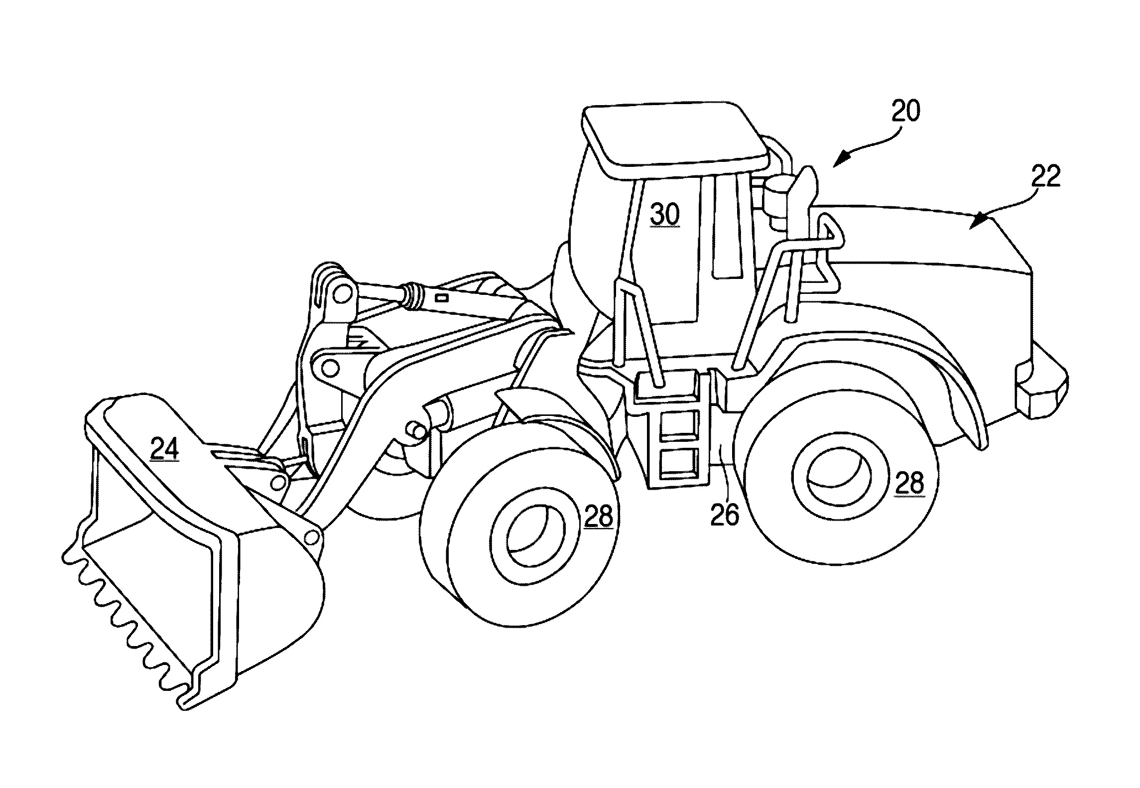
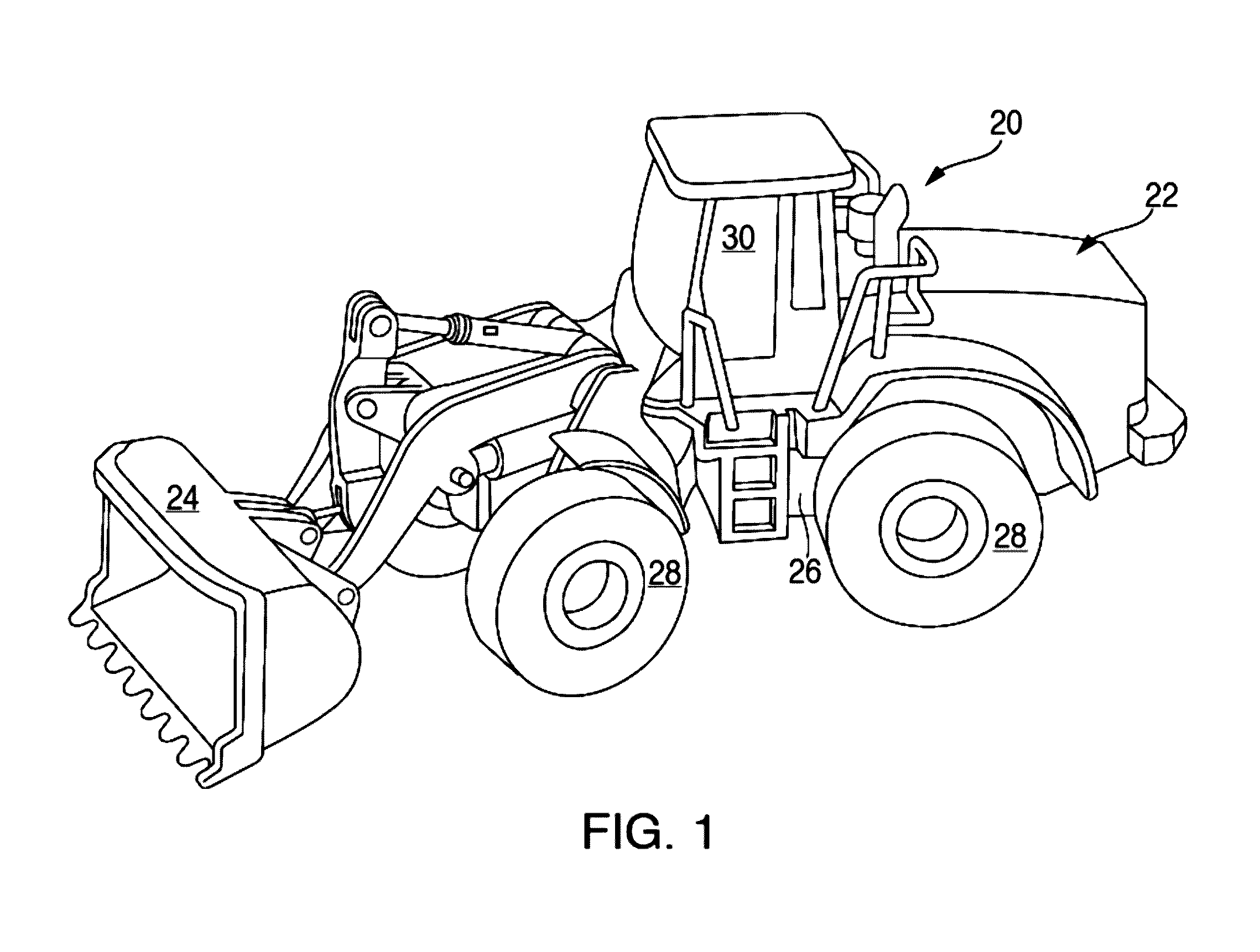
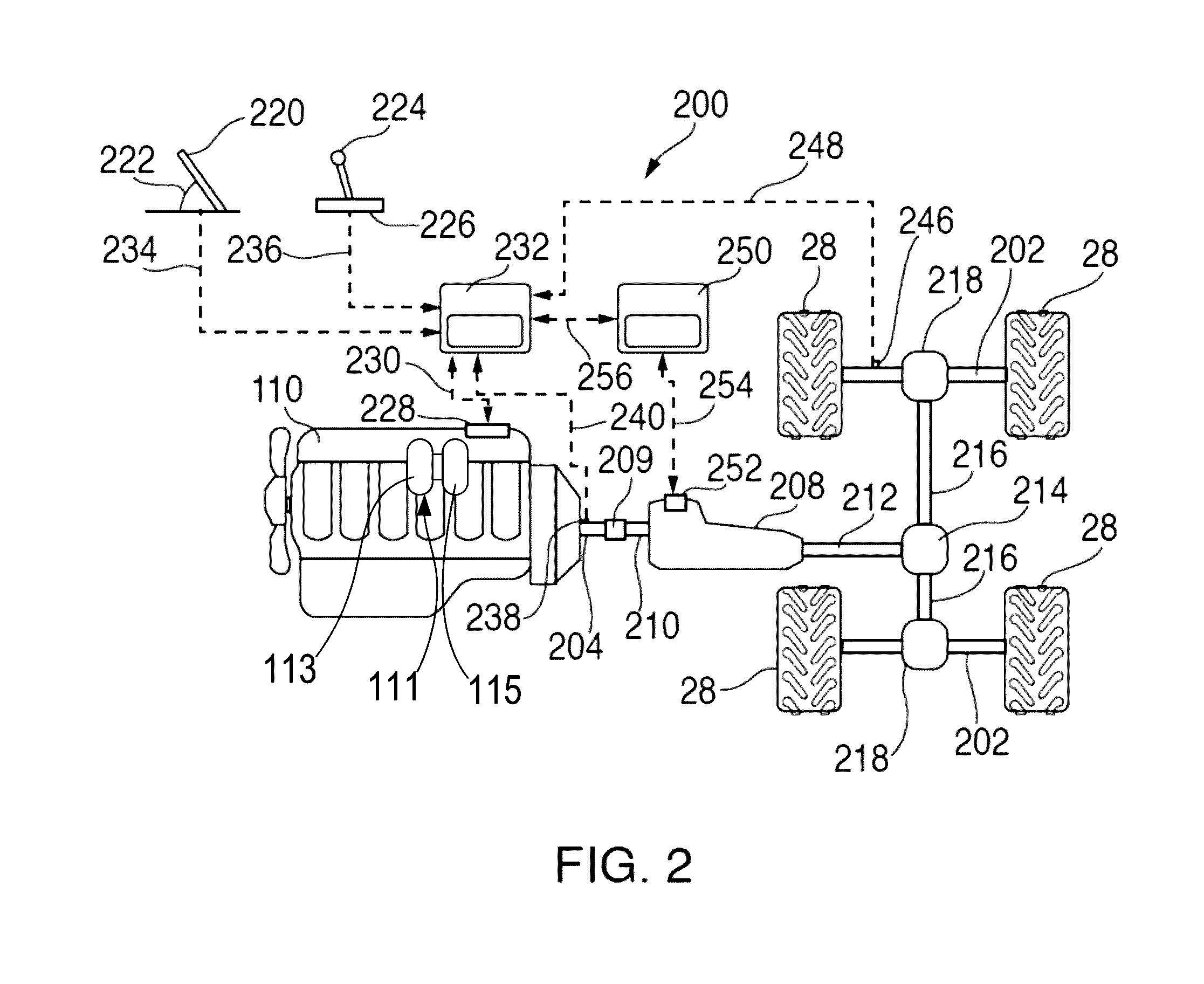
[0017]The present disclosure relates to powertrains and, specifically, to one or more compressors that are associated with one or more turbochargers used on an internal combustion engine. More specifically, the present disclosure describes various embodiments for control strategies that assume or affect normal engine operation, especially during conditions that are known to cause the one or more compressors to surge during engine operation. In one proposed solution, for example, for a wheel loader application, includes maintaining a mass flow of air through the compressor above a surge limit by, during an engine speed and load drop, maintaining the engine speed higher.

[0018]In general, during operation of a turbocharged engine, the turbine extracts energy from the exhaust and drives the compressor. When load is suddenly reduced, the exhaust energy drops and the turbine no longer has the power to drive the compressor to keep the speed up, thus the flow rate thru the compressor drops ...


PUM


Abstract

A method for operating an internal combustion engine includes monitoring engine parameters using an electronic controller, determining a surge speed limit for the engine based on a compressor map, determining an offset engine speed based on a margin between the surge speed limit and an engine speed, determining a minimum engine speed based on the margin, applying the offset engine speed to an engine speed signal to provide an adjusted engine speed, and applying the adjusted engine speed to a desired engine speed when a speed of the engine approaches the surge speed limit.

Description

TECHNICAL FIELD[0001]This patent disclosure relates generally to internal combustion engines and, more particularly, to engine speed control strategies.BACKGROUND[0002]Engines sometimes use turbochargers to extract work from engine exhaust gas and transfer at least some of the extracted work to a compressor, which operates to increase engine boost pressure and, thus, engine power. Because one or more turbochargers can be associated with an engine, and turbocharger operation directly relates to gas and air pressures in the engine exhaust and intake systems, operation of the turbocharger itself can be affected by the engine operating conditions. When the engine operating conditions are changing with time, which are generally referred to as transient engine operating conditions, the various system pressures and air flow or exhaust flow rates may change, which will cause corresponding changes to the turbocharger input and output conditions, in this way affecting the efficiency of the tu...

Claims


Application Information

Patent Timeline
Patent Type & Authority Applications(United States)
IPC IPC(8): F02D41/00F02D41/26
CPCF02D41/26F02D41/0007F02B2037/125F02D31/001F02D41/0225F02D41/18Y02T10/12
Inventor JOSHI, URVISHBARNES, TRAVISCLER, ERIC W.KRISHNAMURTHYGOPALAN, ANANDHUTCHISON, ERIC A.TAMHANE, KIRTISCHIFFERER, ANDREW N.BOWMAN, TYLERSERGOTT, KEVINMOWERS, MATTHEWPUCKETT, DANIEL R.
Owner CATERPILLAR INC
Why Eureka
Eureka Blog
Learn More