Fluid-actuated flow control valves

a flow control valve and actuator technology, applied in the direction of diaphragm valves, engines, instruments, etc., can solve the problems of affecting the flow rate, mechanical stability and precision, and prone to significant wear of the needle over the needle cavity of the highest performing “metering needle valve”

Active Publication Date: 2016-11-24
SUNDEW TECH
View PDF0 Cites 10 Cited by
  • Summary
  • Abstract
  • Description
  • Claims
  • Application Information

AI Technical Summary

Benefits of technology

[0019]Aspects of the invention are directed to an apparatus for controlling a flow of a fluid therethrough while the apparatus is connected to a source of control fluid. The apparatus comprises an input, a valve seat, a diaphragm, an output, and a diaphragm control space. The diaphragm control space is partially defined by the diaphragm, and is operative to receive control fluid from the source of control fluid. Moreover, a deflection of the diaphragm in relation to the valve seat is responsive to a pressure of the control fluid in the diaphragm control space. Lastly, the deflection of the diaphragm in relation to the valve seat is operative to control a fluidic flow resistance between the input and the output.
[0020]Additional aspects of the invention are directed to a method for controlling a flow of a fluid. The method comprises providing an input, a valve seat, a diaphragm, an output, and a diaphragm control space. The diaphragm control space is partially defined by the diaphragm, and is operative to receive control fluid from a source of control fluid. Moreover, a deflection of the diaphragm in relation to the valve seat is responsive to a pressure of the control fluid in the diaphragm control space. Lastly, the deflection of the diaphragm in relation to the valve seat is operative to control a fluidic flow resistance between the input and the output.

Problems solved by technology

However, in many practical flow control systems, the combination of temperature and pressure instability, as well as the finite precision and accuracy of the flow control valve, may prohibit the attainment of adequately stable and / or repeatable flow rate.
Given the nonlinearity, as well as limitations of mechanical stability and precision, most manually driven, precision screw-based valves resort to designs that increase the surface area of the gap.
However, highest performing “metering needle valves” are prone to significant wear of the needle over the needle cavity.
This wear is especially pronounced when controlling the small gaps that provide flow rates lower than 5% of the maximum flow.
Such wear results in both reduced valve performance and the generation of particles.
Particles that are generated in the flow control system and consequentially delivered into the process via streams of fluids are detrimental to the quality of many industrial manufacturing applications and are therefore undesirable.
The precision of a manual flow control valve is adversely impacted by temperature and pressure instabilities as well as potentially fluctuating impact of downstream components.
Therefore, they have growingly become inadequate for precision manufacturing.
Nevertheless, linear gap tuning produces nonlinear flow change.
However, both PI or PID control algorithms, as well as other control algorithms known in the art, are not suitable for accurate and responsive control of nonlinear systems.
Particularly, nonlinearity makes flow control parameters flow dependent.
That means that, for a given set of flow control parameters (i.e., particular PI or PID constants), controllers cannot accurately control the actual flow to match a set point beyond the single flow rate that was selected to initially tune the system and extract the PI or PID constants.
Using these same flow control parameters to control other flow rates often yields erroneous and sometimes oscillatory flow rates, as well as substantially slower response.
Likewise, erroneous and oscillatory flow rates may also be driven by temperature and inlet pressure change, drift, or other fluctuations.
Due to nonlinearity, the shifts in the flow to gap dependence detunes the control system into lower performance, which results in sluggish response, increased error and tendency for oscillations.
Even so, however, the mixing ratio is nevertheless undefined and unstable during transitions between different settings.
Likewise, implementing temperature compensation and integrating inlet pressure control may tame the adverse impact of fluctuating or drifting temperature and / or inlet pressure.
That said, range limitations still create the need for many different and distinctive models of flow control valves, and thereby substantially increase inventory size and cost for manufacturers.
Conventional pressure controllers struggle with such demanding applications.
One other challenging application implements flow control valves as pressure controllers to control the pressure of inert gas that is used to provide improved thermal contact to process heaters and improve their isolation from process effluents.
In particular, fragile heaters may be disposed inside a heating chuck wherein heater to chuck contact and / or complete sealing of the heaters inside the chuck is not possible.
Conventional flow control valves struggle with this application.
Here too, conventional flow control valves struggle with such a demanding application.
Often the speed of robotic arms and parts handling has to follow intricate and complex profiles with well-defined acceleration and deceleration profiles.
Existing systems struggle with many of these applications, in particular, when speed is of the essence.
Conventional flow control valves may also struggle to provide reliable operation at high temperatures, to provide reliable low and zero flow performance, and to provide mechanisms for fail safety, that is, mechanisms to automatically shut off when unexpected system conditions are encountered.
With few exceptions, conventional flow control valves do not provide UHP construction with proper resistance to fluid contamination, valve corrosion, particle generation and jamming.
These flow control valves with actuators immersed in the fluids are not suitable to control the flow of most liquids.
These permanent flow restrictors adversely slowed down the rate of purging and decontaminating flow and pressure controllers and their manifolds prior to component replacement and / or the performance of maintenance.

Method used


Image

  • Fluid-actuated flow control valves
  • Fluid-actuated flow control valves
  • Fluid-actuated flow control valves

Examples


Embodiment Construction

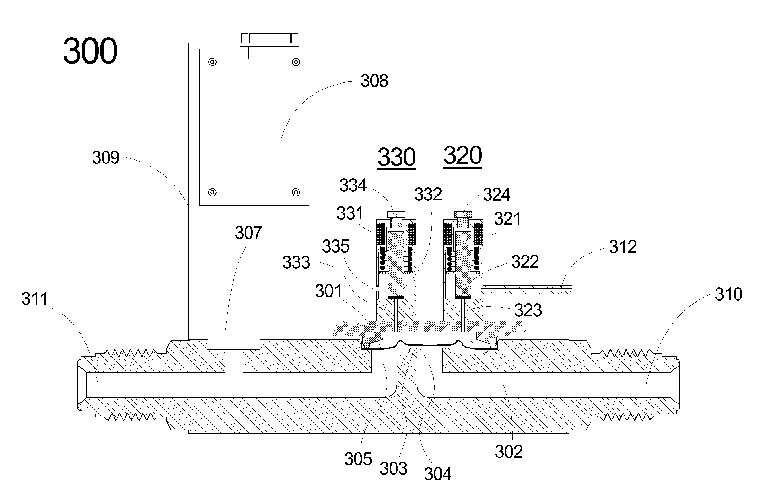
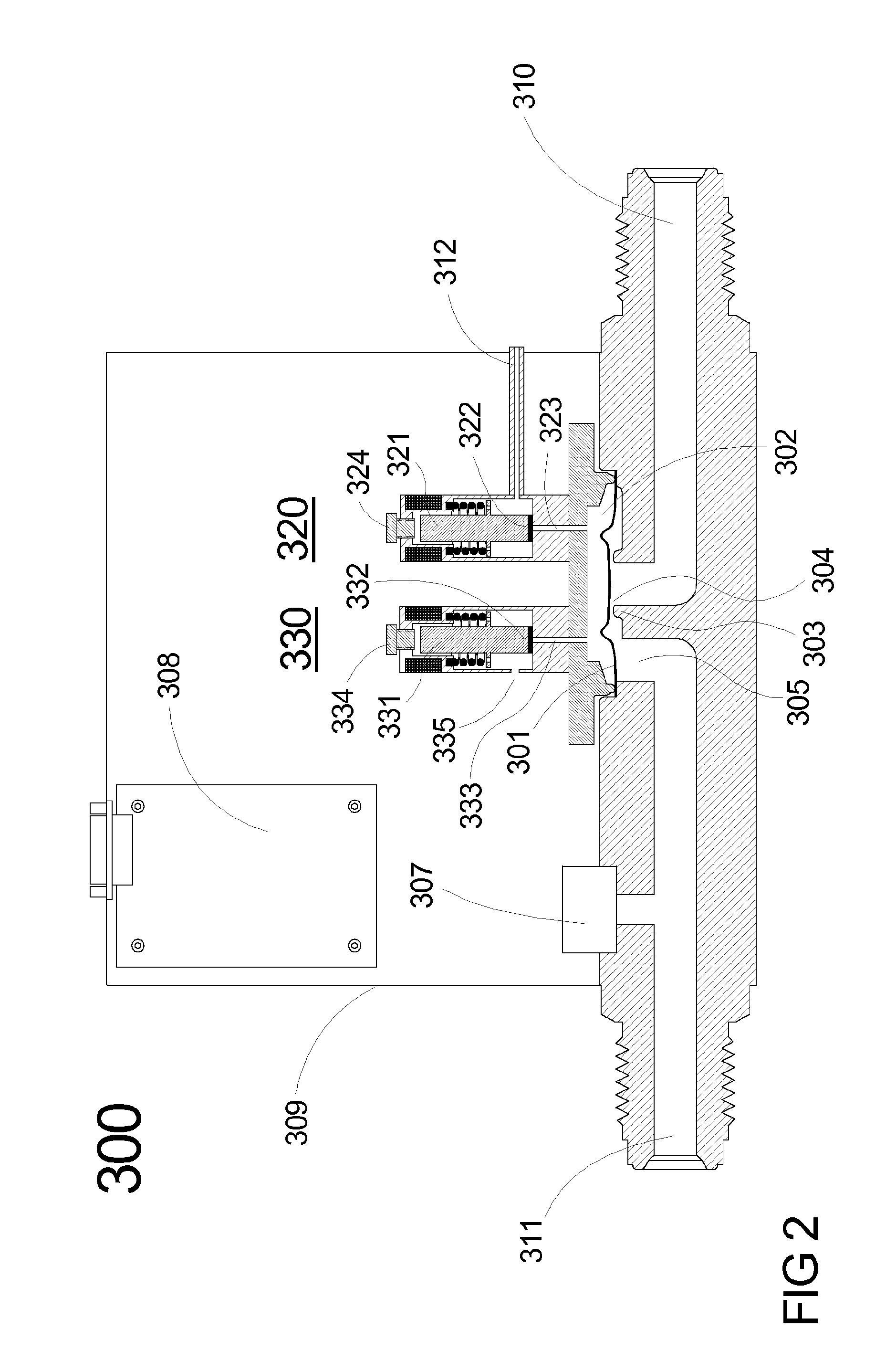
[0043]While conventional flow and pressure control valves utilize mechanical means for deflecting a diaphragm in relation to a valve seat to affect orifice geometry, aspects of the invention instead utilize the pressure of a control fluid on a diaphragm to produce a similar effect. FIG. 2 shows a sectional view of a flow control valve 300 in accordance with a first illustrative embodiment of the invention. The flow control valve 300 comprises a metallic diaphragm 301 disposed so as to seal the flow path between valve seat 303 and fluid outlet port 305. Orifice 304 is thereby formed between diaphragm 301 and valve seat 303. A sealed diaphragm control space 302 is formed above diaphragm 301 and is partly defined by the diaphragm 301. The diaphragm control space 302 comprises control fluid inlet 323 and control fluid outlet 333. The flow control valve 300 also includes a flow or pressure sensor 307, inlet fitting 310, outlet fitting 311, control fluid inlet 312, solenoid valve 320, sol...


PUM


Abstract

Aspects of the invention are directed to an apparatus for controlling a flow of a fluid therethrough while the apparatus is connected to a source of control fluid. The apparatus comprises an input, a valve seat, a diaphragm, an output, and a diaphragm control space. The diaphragm control space is partially defined by the diaphragm, and is operative to receive control fluid from the source of control fluid. Moreover, a deflection of the diaphragm in relation to the valve seat is responsive to a pressure of the control fluid in the diaphragm control space. Lastly, the deflection of the diaphragm in relation to the valve seat is operative to control a fluidic flow resistance between the input and the output.

Description

FIELD OF THE INVENTION[0001]This invention relates to the field of fluid delivery and, more specifically, to apparatus and methods for the flow-controlled delivery of gases and liquids.BACKGROUND OF THE INVENTION[0002]Fluids (i.e., gases and liquids) are used in many manufacturing industries. Within a manufacturing process, fluids are typically dispensed with precision of flow rate, timing or both. Generally, fluid dispensing equipment has the ability to adjust the flow rate by means of flow control valves. A flow control valve regulates the opening of a flow path (i.e., an orifice) to suit the necessary flow rate.[0003]In addition to the orifice, the flow rate also depends on the properties of the fluid, as well as its temperature and pressure. For a given fluid at steady temperature and pressure, stable flow rates may be determined simply by the setting of the flow control valve. However, in many practical flow control systems, the combination of temperature and pressure instabili...

Claims


Application Information

Patent Timeline
Patent Type & Authority Applications(United States)
IPC IPC(8): F16K31/40F16K31/128F16K7/17
CPCF16K31/402F16K31/128F16K7/17F16K7/16G05D7/005G05D7/0113
Inventor SNEH, OFER
Owner SUNDEW TECH
Why Eureka
Try Eureka