Handwheel cap

a technology of handwheel and handle, which is applied in the direction of diaphragm valves, valve details, valve arrangements, etc., can solve the problems of inability to move the handle with all their strength, the valve handle cover cannot be fitted to the valve, and the unspecified large number of people cannot easily access the valve, so as to reduce the turning for

Inactive Publication Date: 2016-11-24
FUJIKIN INC
View PDF10 Cites 4 Cited by
  • Summary
  • Abstract
  • Description
  • Claims
  • Application Information

AI Technical Summary

Benefits of technology

[0029]The handwheel cap according to the present invention is capable of being attached to the handwheel, with the internal casing of the cap so fitted to the rotating shaft of the handwheel that the internal casing extends along the rotating shaft. Thus the present invention eliminates the necessity of space expanding in the directions perpendicular to the rotating shaft of the handwheel for the attachment of the cap to the handwheel. The handwheel cap according to the present invention is provided with the clutch capable of making the external casing rotatable around the rotation axis thereof independently of the internal casing, and also with the maintaining member capable of keeping the external casing rotatable in relation to the internal casing, or independently of the internal casing. As a result, when rotating force is applied to the external casing and the external casing is rotated, the rotation of the external casing is not transmitted to the internal casing, which achieves the state where only the external casing is rotated with the internal casing remaining unrotated. On the other hand, when the internal casing and the external casing are co-rotated by means of the clutch and the maintaining member, the handwheel is also rotated. The diameter of the external casing is larger than that of the handwheel, which reduces turning force necessary to rotate the handwheel.
[0029]The handwheel cap according to the present invention is capable of being attached to the handwheel, with the internal casing of the cap so fitted to the rotating shaft of the handwheel that the internal casing extends along the rotating shaft. Thus the present invention eliminates the necessity of space expanding in the directions perpendicular to the rotating shaft of the handwheel for the attachment of the cap to the handwheel. The handwheel cap according to the present invention is provided with the clutch capable of making the external casing rotatable around the rotation axis thereof independently of the internal casing, and also with the maintaining member capable of keeping the external casing rotatable in relation to the internal casing, or independently of the internal casing. As a result, when rotating force is applied to the external casing and the external casing is rotated, the rotation of the external casing is not transmitted to the internal casing, which achieves the state where only the external casing is rotated with the internal casing remaining unrotated. On the other hand, when the internal casing and the external casing are co-rotated by means of the clutch and the maintaining member, the handwheel is also rotated. The diameter of the external casing is larger than that of the handwheel, which reduces turning force necessary to rotate the handwheel.
[0029]The handwheel cap according to the present invention is capable of being attached to the handwheel, with the internal casing of the cap so fitted to the rotating shaft of the handwheel that the internal casing extends along the rotating shaft. Thus the present invention eliminates the necessity of space expanding in the directions perpendicular to the rotating shaft of the handwheel for the attachment of the cap to the handwheel. The handwheel cap according to the present invention is provided with the clutch capable of making the external casing rotatable around the rotation axis thereof independently of the internal casing, and also with the maintaining member capable of keeping the external casing rotatable in relation to the internal casing, or independently of the internal casing. As a result, when rotating force is applied to the external casing and the external casing is rotated, the rotation of the external casing is not transmitted to the internal casing, which achieves the state where only the external casing is rotated with the internal casing remaining unrotated. On the other hand, when the internal casing and the external casing are co-rotated by means of the clutch and the maintaining member, the handwheel is also rotated. The diameter of the external casing is larger than that of the handwheel, which reduces turning force necessary to rotate the handwheel.

Problems solved by technology

In other words, the valve is not easily accessible to an unspecified large number of people; even if they try to operate the valve handle by grasping the handle cover with hands, it is impossible for them to move the handle with all their strength.
Therefore a technical problem of this device is that the valve handle cover cannot be fitted to the valve unless a sufficiently large space is saved around the valve.

Method used


Image

  • Handwheel cap
  • Handwheel cap
  • Handwheel cap

Examples


Embodiment Construction

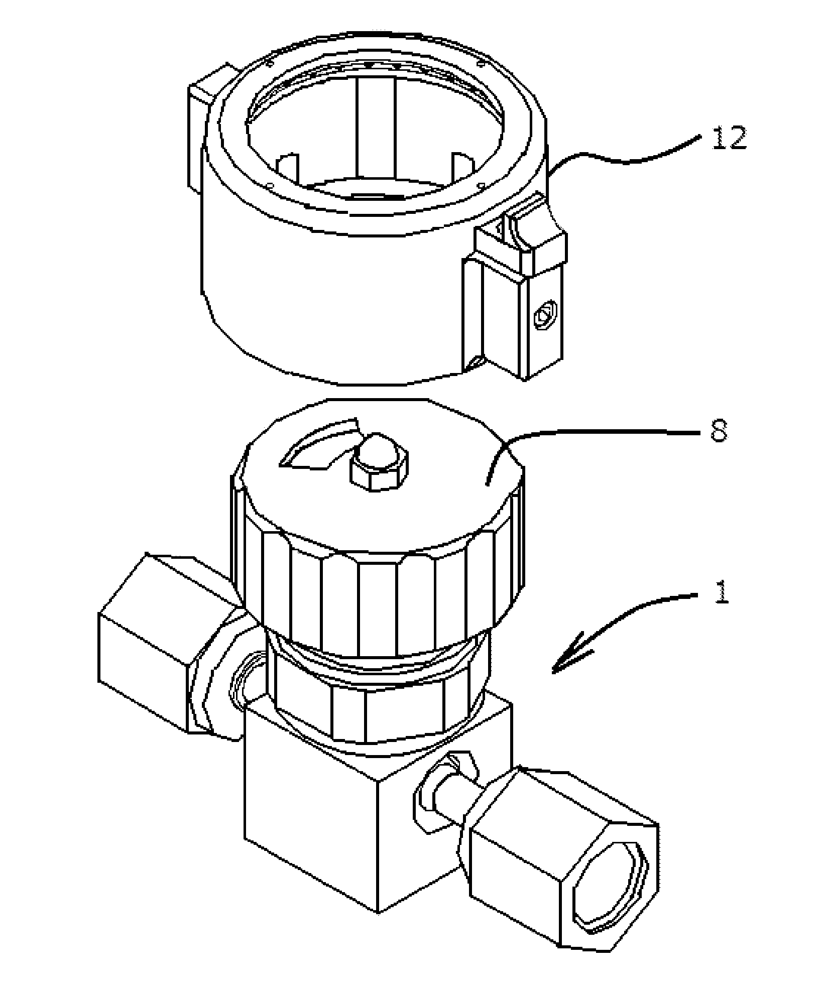
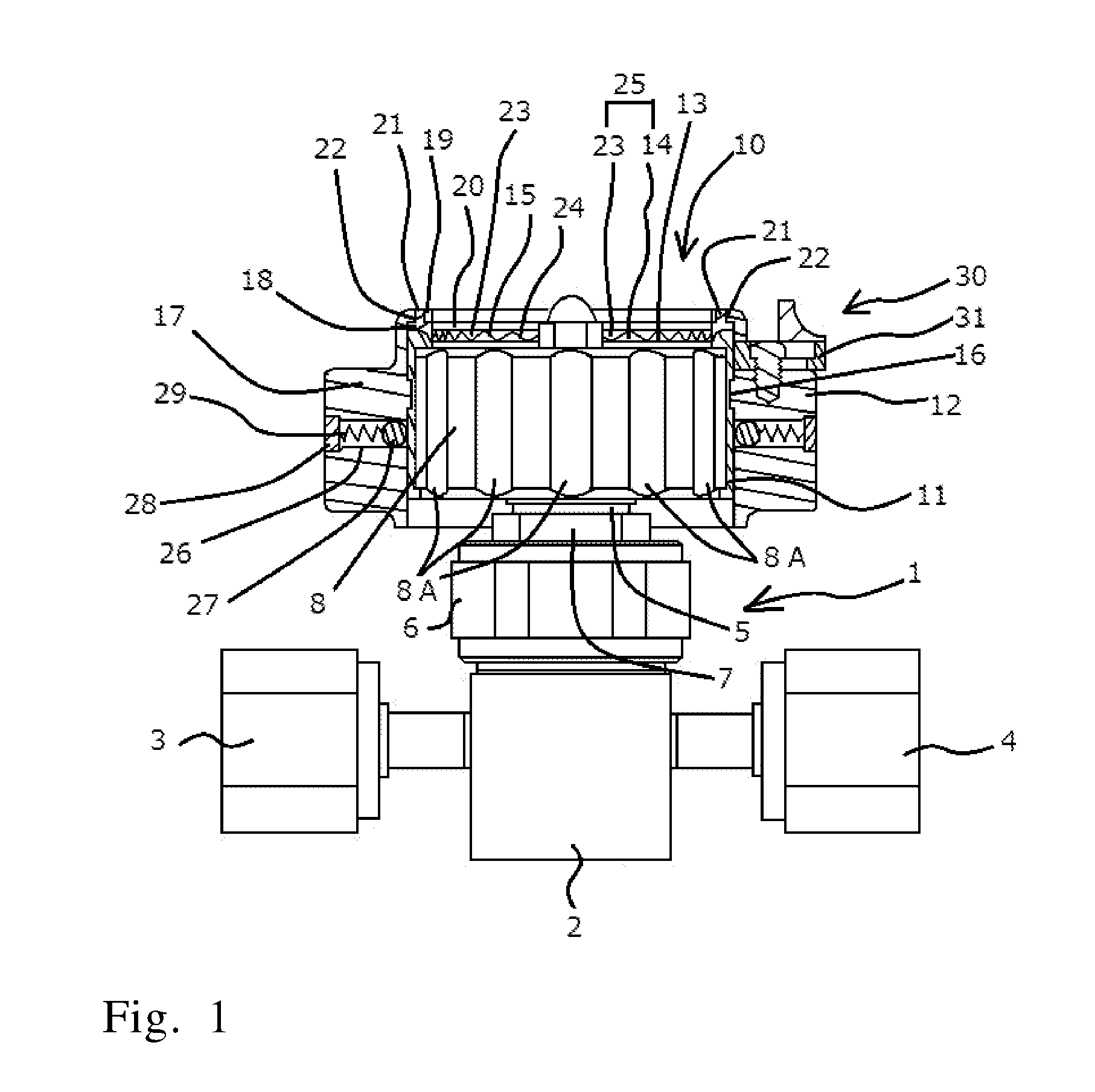
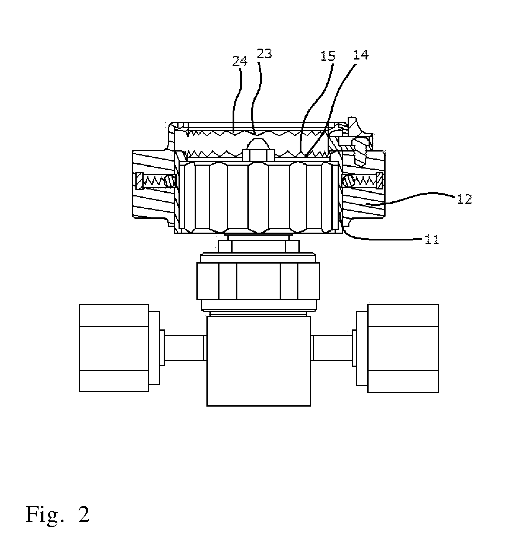
[0038]Fluid controllers to which a handwheel cap, an example of the present invention, is attached will be explained.

[0039]As shown in FIGS. 1-3, a fluid controller 1 may be, for example, a known diaphragm valve which comprises a main body 2 of the fluid controller, which is also called a body, having an inlet joint 3 and an outlet joint 4; a bonnet 5 in the shape of a general tube, the bonnet so fitted to a top part of the main body 2 that the bonnet covers part of the top part; a bonnet nut 6 for fixing the bonnet 5 to the main body 2 of the fluid controller; a panel nut 7 placed around the bonnet 5; a handwheel 8 rotatable clockwise and counterclockwise; a valve stem (not shown in the figures), which is a rotating shaft moving upward and downward according to the rotation of the handwheel 8; and a diaphragm (not shown in the figures) which allows communication between the inlet port and the outlet port, both in the main body 2 of the fluid controller, or blocks the communication ...


PUM


Abstract

Provided is a cap for a handwheel that opens and closes a valve, capable of being readily attached to the handwheel without requiring a large space around the handwheel. The cap has easily switchable two working modes: One is a co-rotation mode where the cap is capable of rotating with the handwheel and the other is an independent rotation mode where the cap is capable of rotating independently of the handwheel. The cap has an internal casing to be securely fitted to the handwheel; an external casing being rotatable around its axis and having the internal casing in an interior thereof; a clutch for connecting the external casing with the internal casing and for disconnecting the former from the latter; and a maintaining member for keeping the external casing rotatable independently of the internal casing when they are disconnected by the clutch.

Description

TECHNICAL FIELD[0001]The present invention relates to a handwheel cap. More particularly, the invention relates to a handwheel cap capable of being readily attached to a handwheel even if the space surrounding the handwheel is small. The handwheel cap has two working modes: One is a co-rotation mode where the handwheel cap is capable of rotating with the handwheel, and the other is an independent rotation mode where the handwheel cap is capable of rotating independently of the handwheel. Once the handwheel cap is attached to the handwheel, the modes are switchable by a simple operation.[0002]BACKGROUND ART[0003]Conventional technology associated with valves includes a proposal for a cover for a handle of a valve to “prevent wrong operation of a handle of a valve included in the parts of machinery and equipment” (see patent document 1).[0004]Patent document 1 discloses a valve handle cover whose general features are clearly understood from the figures thereof. Specifically, a valve h...

Claims


Application Information

Patent Timeline
Patent Type & Authority Applications(United States)
IPC IPC(8): F16K35/02F16K31/60
CPCF16K35/02F16K31/60F16K7/00F16K35/04F16K31/44F16K51/00
Inventor IWANAGA, YUSUKESATO, HIDENOBUMATSUDA, TAKAHIRO
Owner FUJIKIN INC
Why Eureka
Try Eureka