Lever for drive-by-wire system

A lever, telex technology, used in transmission control, control/regulation systems, steering controls mounted on the car, etc., can solve ankle injuries, the shift lever can not be freely set buttons, the driver is steered by the wheel. Injury and other problems, to achieve the effect of reducing vehicle cost and improving operating characteristics

Inactive Publication Date: 2016-03-02
HYUNDAI MOTOR CO LTD
View PDF6 Cites 2 Cited by
  • Summary
  • Abstract
  • Description
  • Claims
  • Application Information

AI Technical Summary

Problems solved by technology

[0008] However, the fly-by-wire system of the vehicle of the related art has a problem that the vehicle of the related art itself has in that the mechanical connecting structure is only replaced by the electrical connecting structure without manipulation capable of maximizing the benefit of the fly-by-wire system. mechanism
[0009] That is to say, there is such a problem that when a vehicle collides with a vehicle, the driver is injured by the steering wheel; when the driver manipulates the accelerator pedal and the brake pedal with the right foot, there is a risk of an accident due to wrong manipulation. ; and there is also the problem that when the vehicle is driving on the highway or driving a long distance, the driver repeatedly operates the pedals, which can cause ankle injuries
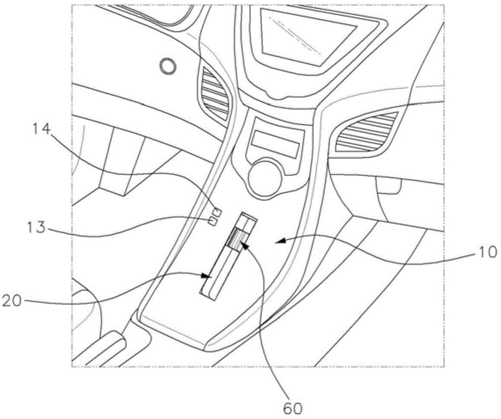
[0010] There is also a problem that buttons, etc. for performing functions necessary for driving a vehicle cannot be freely arranged around the shift lever because the shift lever protrudes from the console surface even at ordinary times.

Method used


Image

  • Lever for drive-by-wire system
  • Lever for drive-by-wire system
  • Lever for drive-by-wire system

Examples


Embodiment Construction

[0047] Reference will now be made in detail to various embodiments of the invention, examples of which are illustrated in the accompanying drawings and described below. While the invention has been described in conjunction with exemplary embodiments, it will be understood that present description is not intended to limit the invention to those exemplary embodiments. On the contrary, the invention is intended to cover not only the exemplary embodiments, but also alterations, modifications, equivalents and other embodiments as included within the spirit and scope of the invention as defined by the claims.

[0048] Next, the present invention will be specifically described with reference to the accompanying drawings so that those skilled in the art to which the present invention pertains can easily implement the present invention. However, the present invention can be implemented in various ways and is not limited to the exemplary embodiments described herein.

[0049] Parts not...


PUM


Abstract

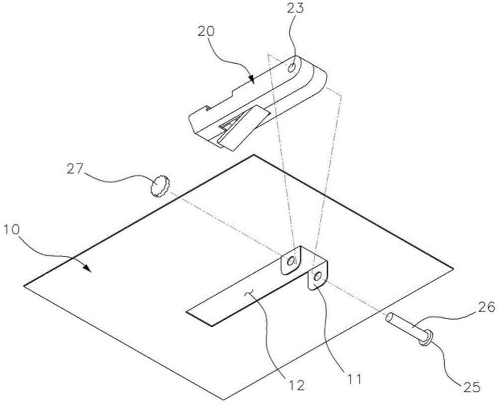
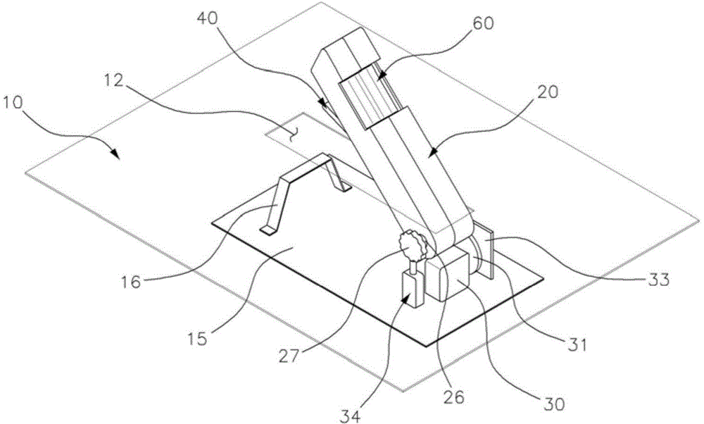
A lever for a drive-by-wire system installed in a vehicle, may include a lever body that is rotatably mounted on a console surface of the vehicle, and an acceleration lever and a steering roller that are installed in the lever body, such that it is possible to control a change of a gear shift stage, acceleration, and a change of a proceeding direction of the vehicle in a unified manner, and there is no risk of erroneous manipulations of an accelerator pedal and a brake pedal, and acceleration and a proceeding direction may be changed using a finger, thereby improving performance in manipulating the vehicle.

Description

[0001] Cross References to Related Applications [0002] This application claims priority from Korean Patent Application No. 10-2014-113864 filed on Aug. 29, 2014, the entire contents of which are hereby incorporated by reference for all purposes. technical field [0003] The present invention relates to a control lever for a drive-by-wire system installed in a vehicle, and more particularly to such a control lever for a drive-by-wire system, wherein The lever body is rotatably mounted on the console surface of the vehicle, and the accelerator control lever and the steering roller are mounted in the lever body, so that the vehicle's shift gear change, acceleration and travel direction change can be controlled in a unified manner. Background technique [0004] In general, a fly-by-wire system (so-called X-by-wire system) applied to a vehicle refers to a system in which an electrical connection structure of an actuator, an electronic control unit (ECU), etc. is used Replaces ...

Claims


Application Information

Patent Timeline
Patent Type & Authority Applications(China)
IPC IPC(8): B60K26/02B62D1/02B60K20/02
CPCB60K20/08B60K26/02B60K2026/029B62D1/12G05G1/04F16H61/00F16H61/26F16H61/28B60K23/00G05G1/34
Inventor 金恩植
Owner HYUNDAI MOTOR CO LTD
Why Eureka
Try Eureka