
Korsch-type compact three-mirror anastigmat telescope

a compact, three-mirror technology, applied in the field of telescopes, can solve the problems of increasing geometrical astigmatism and eccentricity coma aberrations which are not generally acceptable, and reducing the field of korsch-type telescopes. , to achieve the effect of improving the field of korsch-type telescopes, improving quality, and improving the correction of optical aberrations

Active Publication Date: 2016-11-24
THALES SA
View PDF1 Cites 11 Cited by
  • Summary
  • Abstract
  • Description
  • Claims
  • Application Information

AI Technical Summary

Benefits of technology

The patent text describes a method to improve the image quality of a microscope or other optical instruments. The method involves steps to eliminate blurring caused by the rotation of the main mirror and to modify the shape of the mirror to correct the image. These steps help to improve the clarity and accuracy of the image and reduce the impact of any distortion.

Problems solved by technology

In effect, the mirrors can be tilted to eliminate the central occulting, but this solution adds geometrical astigmatism and eccentricity coma aberrations which are not generally acceptable.
This optical solution makes it possible to reduce the field off-axis margin and / or pupil margin, but not totally eliminate them.
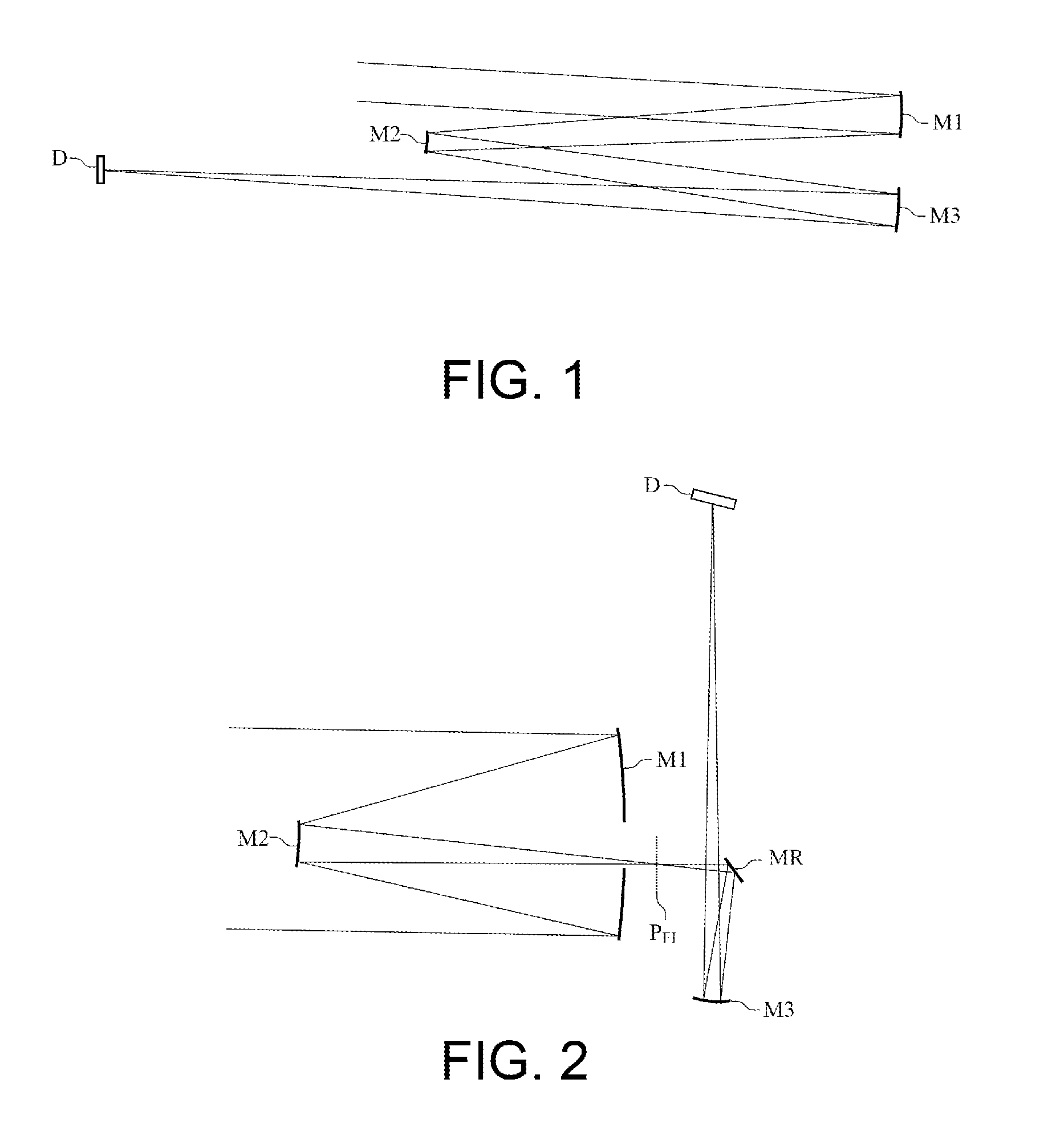
However, with given focal length, their bulk is sizeable and becomes prohibitive for certain applications, particularly when the pupil of the telescope has a significant diameter or when the focal length is significant.
Unfortunately, their field is limited.
Thus, the linear field cannot readily exceed three degrees.
Now, these surfaces are not perfectly adapted to correct the aberrations of optical systems which no longer have an axis of symmetry like the TMA or Korsch telescopes.
However, they are not used on their optical axis, but in the field.
The TMAs are perfectly corrected of the aberrations at the centre of the field, on the optical axis, but the occulting renders this point of the field inaccessible.
The more the distance from the optical centre increases, the more the image quality decreases because the system is not perfectly corrected of the aberrations.
This error is no longer compatible with the performance levels required.
This is a first limitation.
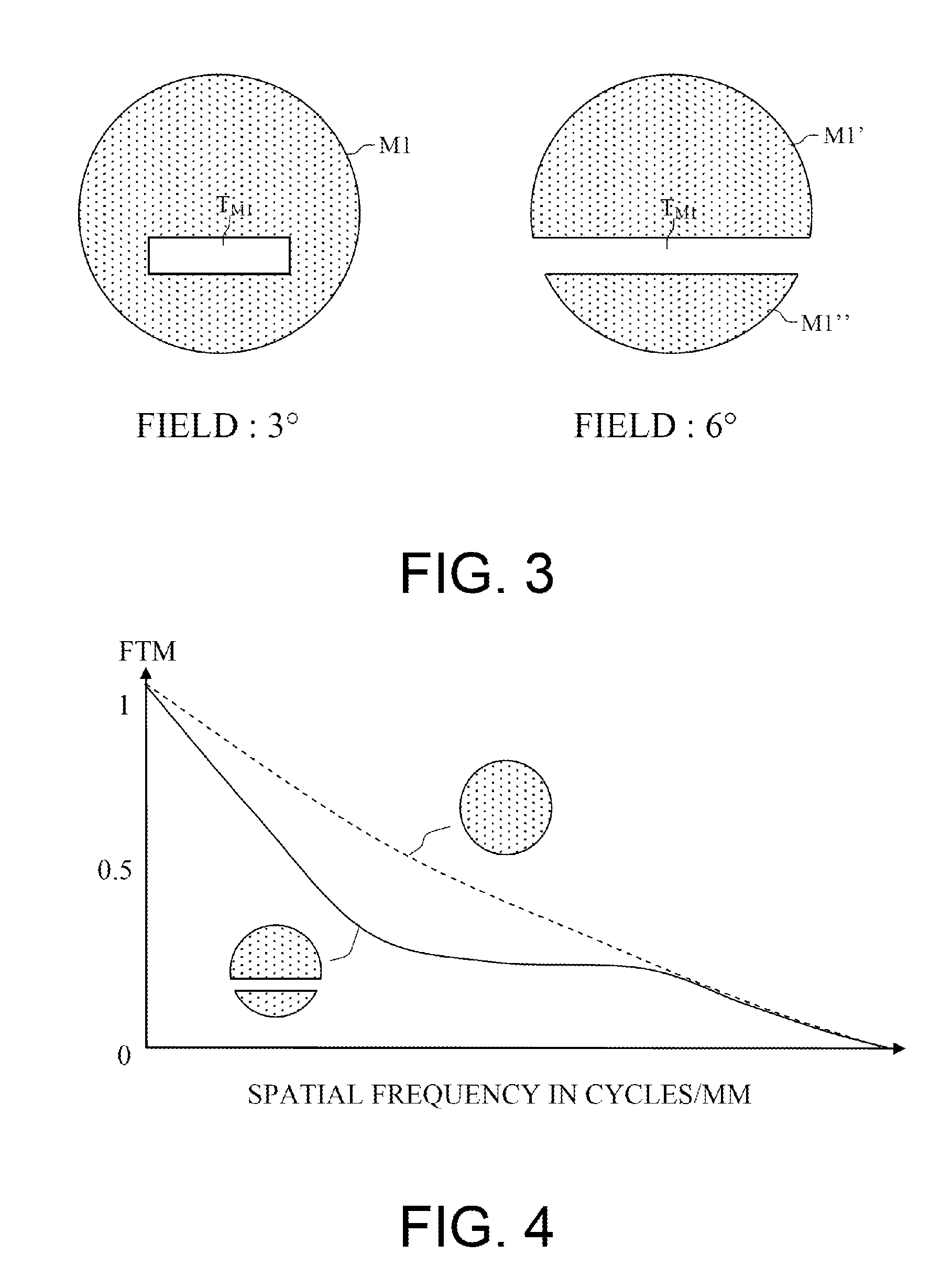
The first drawback associated with the presence of this opening is a reduction of the useful surface area of the primary mirror of the order of 15 to 20%.
The second drawback is of a mechanical nature.
For a field less than 3°, the hole dimension is acceptable, but if the field of view is increased, the size of the hole becomes significant and makes it necessary to produce the mirror M1 in two distinct parts, which poses significant mechanical problems.
This optical solution makes it possible to achieve significant fields but does not have the requisite compactness.
This optical solution makes it possible to achieve significant fields but, hereagain, does not have the requisite compactness when the focal length is of significant size.

Method used


Image

  • Korsch-type compact three-mirror anastigmat telescope
  • Korsch-type compact three-mirror anastigmat telescope
  • Korsch-type compact three-mirror anastigmat telescope

Examples


Embodiment Construction

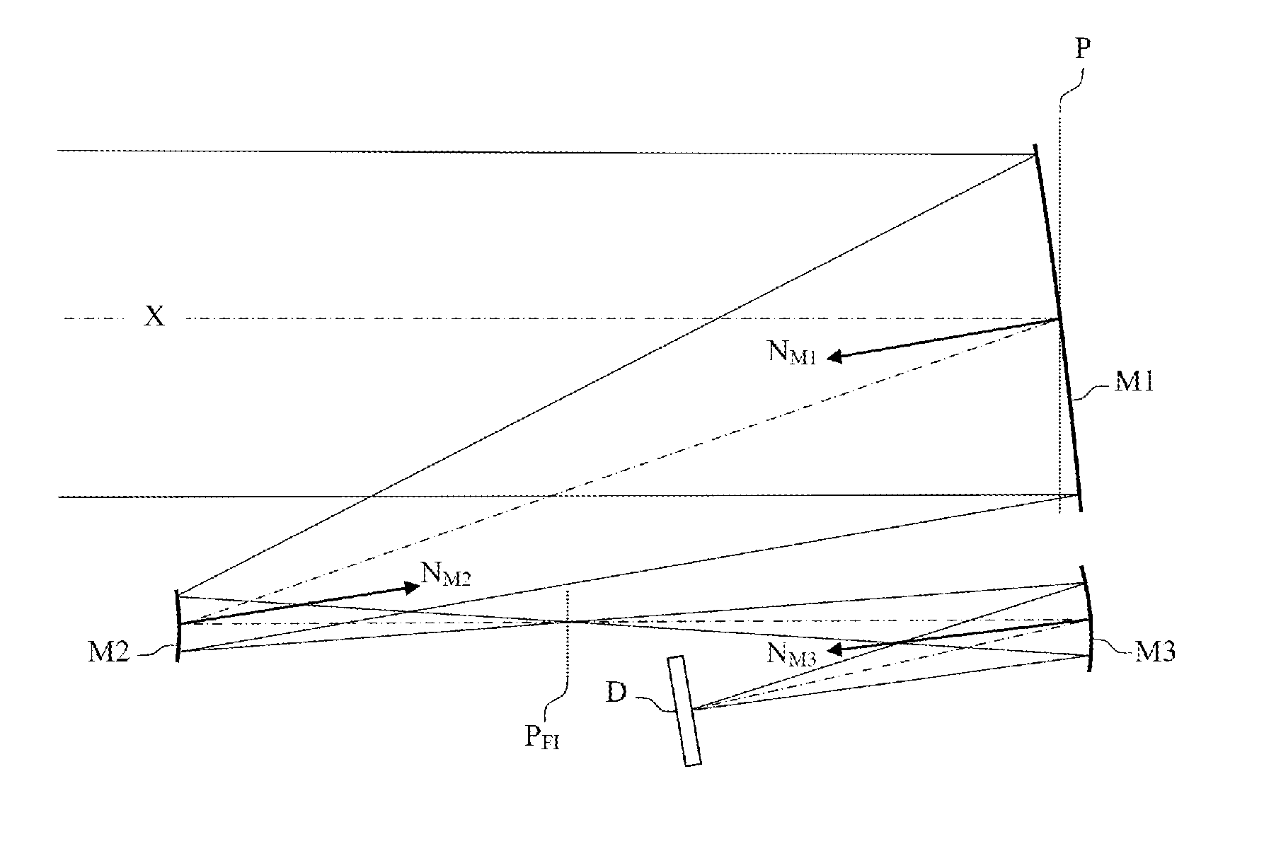
[0050]By way of example, FIG. 7 represents an optical architecture of three-mirror anastigmat telescopes according to the invention. This architecture comprises a concave first mirror M1, a convex second mirror M2 and a concave third mirror M3. In this figure, the optical axis X passing through the centre of the pupil P is represented by dotted lines and the normals NM1, NM2 and NM3 to the surface of the mirrors M1, M2 and M3 are represented by arrows arranged at the centre of the mirrors.

[0051]This architecture is derived from the Korsch-type architectures as described previously. However, it is demonstrated that the use of freeform surface mirrors makes it possible to notably increase the accessible anastigmat field. According to the architectures employed, the gain is substantially by a factor 2.

[0052]The three mirrors are arranged so that the first mirror and the second mirror form, from an object at infinity, an intermediate image situated in a focussing plane PFI situated betw...


PUM


Abstract

A three-mirror anastigmat telescope comprises at least a concave first mirror, a convex second mirror and a concave third mirror, the three mirrors arranged so that the first mirror and the second mirror form, from an object at infinity, an intermediate image situated between the second mirror and the third mirror, the third mirror forming, from this intermediate image, a final image in the focal plane of the telescope. In the architecture of the telescope, at least the surface of the concave third mirror is a φ-polynomial surface.

Description

CROSS-REFERENCE TO RELATED APPLICATION[0001]This application claims priority to foreign French patent application No. FR 1501064, filed on May 22, 2015, the disclosure of which is incorporated by reference in its entirety.FIELD OF THE INVENTION[0002]The field of the invention is that of telescopes, and more particularly of observation telescopes embedded in satellites. More specifically, the field of the invention relates to the catoptric systems with great focal lengths.BACKGROUND[0003]There are two forms of angular field according to the type of receiver associated with the telescope. For the linear receivers, the angular field value is a few degrees in a first direction of space and a few tenths of degrees in the perpendicular direction. For the matrix receivers, the angular field value is a few degrees in both directions of space.[0004]The optical architecture of this type of telescope comprises only conventionally off-axis mirrors. This type of architecture makes it possible to...

Claims


Application Information

Patent Timeline
IPC IPC(8): G02B23/06G02B17/06
CPCG02B17/0642G02B23/06G02B17/0626G02B27/0012
Inventor TETAZ, NICOLASVIARD, THIERRY
Owner THALES SA
Learn More