Device and method for protecting an electrical system component of a vehicle electrical system

a technology for electrical systems and components, applied in emergency protection circuit arrangements, testing electric installations on transport, instruments, etc., can solve problems such as latent faults, unusable electrical connections between voltage-conducting electrical lines, and latent faults, and achieve the effect of improving the functional reliability of electrical system components

Active Publication Date: 2016-11-24
LISA DRAXLMAIER GMBH
View PDF5 Cites 4 Cited by
  • Summary
  • Abstract
  • Description
  • Claims
  • Application Information

AI Technical Summary

Benefits of technology

[0011]Embodiments of the present disclosure disclose an option for protecting an electrical

Problems solved by technology

With respect to the short circuits, for example, an undesirable electrical connection between a voltage-conducting electrical line and ground, or an undesirable electrical connection between two electrical lines conducting a voltage, may occur sporadically or permanently and to varying degrees.
If the diagnosis detects that the short circuit detection does not function, for example, then a latent fault is present.
The fault is latent because a short circuit must occur in addition to the failure of short circuit detection for damage to occur.
For a device that protects an electrical system component, the challenge is to satisfy the two safety objectives of protection against thermal overload and availability-relevant supply of safety-critical functions at the same time.
The safe OFF state of the first safety obje

Method used


Image

  • Device and method for protecting an electrical system component of a vehicle electrical system
  • Device and method for protecting an electrical system component of a vehicle electrical system
  • Device and method for protecting an electrical system component of a vehicle electrical system

Examples


Embodiment Construction

[0043]The figures are only schematic representations and are provided only for explaining the present disclosure. Like elements are uniformly denoted by like reference numerals.

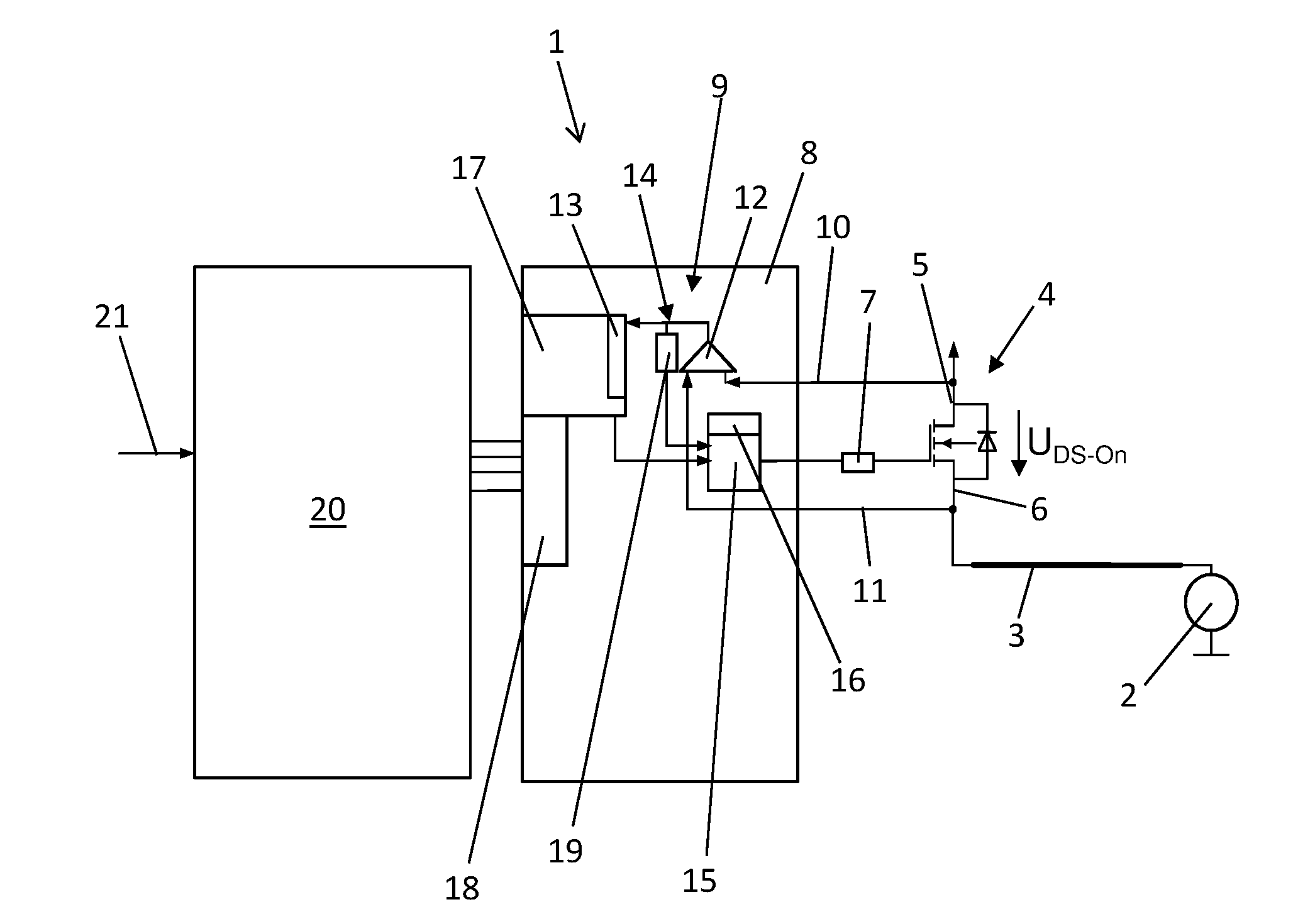
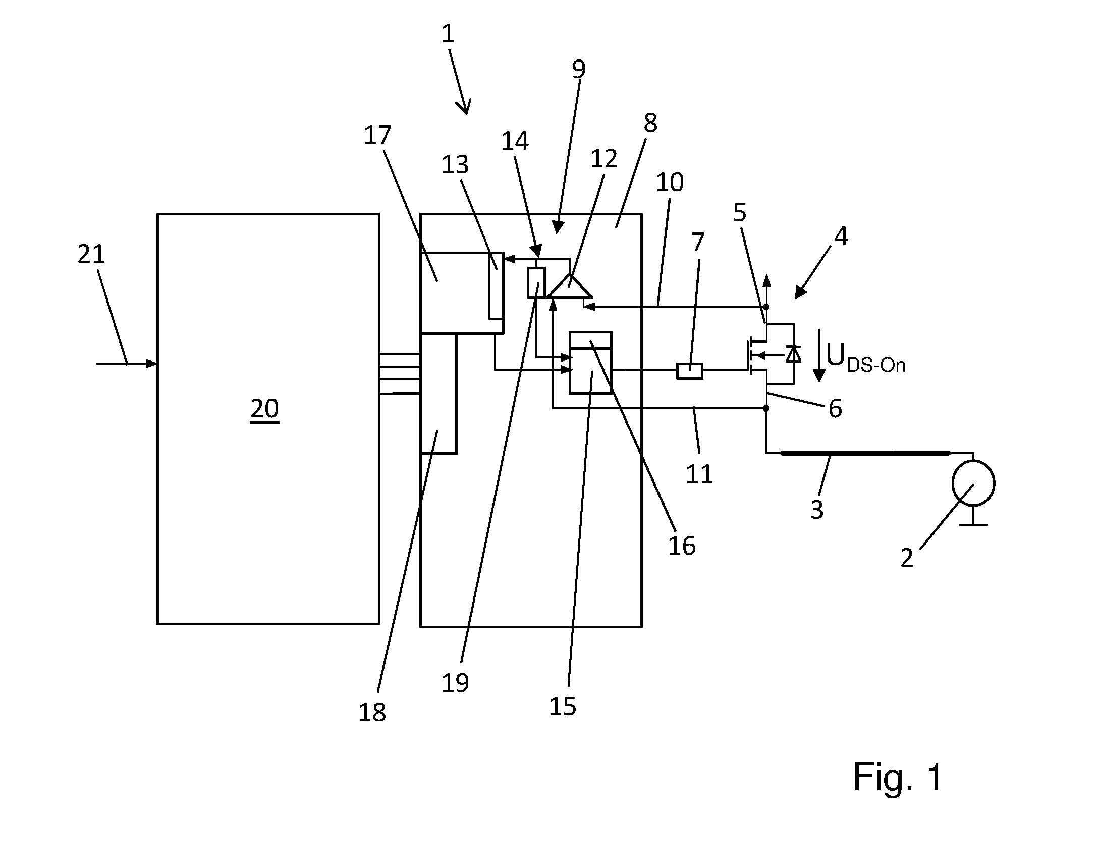
[0044]FIG. 1 shows a schematically illustrated block diagram of an exemplary device 1 according to the present disclosure for protecting at least one electrical system component of a vehicle electrical system (which is shown only in sections here). The vehicle electrical system is an on-board electrical system known as an electrical energy system of a motor vehicle.

[0045]The vehicle electrical system comprises an electrical line 3 connected to an electrical consumer or an electrical load 2. The electrical system component to be protected by the device 1 can be the electrical load 2 or the electrical line 3, or both elements, for example. This exemplary embodiment shows exactly one load channel by way of example.

[0046]FIG. 1 shows the device 1 comprises a semiconductor switch 4, which is connected via the elec...


PUM


Abstract

The invention relates to a device (1) for protecting at least one electrical system component (2, 3) of a vehicle electrical system. The device comprises at least one semiconductor switch (4), which is connected to the at least one electrical system component (2, 3) in an electrically conductive manner. Additionally, a circuit (8) is provided, which is connected to the semiconductor switch (4) in an electrically conductive manner and which comprises a detection unit (9) for detecting an electrical malfunction of the vehicle electrical system and an activation unit (14) for activating the semiconductor switch (4). The device (1) furthermore includes a control unit (20), which is communicatively connected to at least the circuit (8). According to the invention, the device (1) is configured to switch the semiconductor switch (4) into a first safe state, in which the semiconductor switch (4) is switched off, as a function of the detection of an electrical malfunction, and furthermore to selectively switch the semiconductor switch into the first safe state or into a second safe state, in which the semiconductor switch (4) is switched on, as a function of at least one predetermined vehicle state. The invention further relates to a method for protecting at least one electrical system component (2, 3) of a vehicle electrical system.

Description

CROSS REFERENCE TO RELATED APPLICATION[0001]This application is based upon and claims the benefit of prior German Patent Application No. 10 2015 107 718.3, filed on May 18, 2015, the entire contents of which are incorporated herein by reference.TECHNICAL FIELD[0002]The present disclosure relates to a device for protecting at least one electrical system component of a vehicle electrical system, such as an on-board electrical system or an electrical energy system of a motor vehicle, hybrid vehicle or electric vehicle. The present disclosure further relates to a method for protecting at least one electrical system component of such a vehicle electrical system.BACKGROUND OF THE DISCLOSURE[0003]Vehicle electrical systems are used to supply a plurality of electrical consumers or loads with electric energy. Semiconductor switches, for example, can be used as high-side switches for switching these loads, which selectively supply the respective consumers with electric energy or shut the load...

Claims


Application Information

Patent Timeline
IPC IPC(8): H02H3/08G01R31/02G01R19/165
CPCH02H3/08G01R31/02G01R19/165G01R31/007H02H3/087
Inventor WORTBERG, MICHAELBACHMEIER, ANTONEDERER, ANTON
Owner LISA DRAXLMAIER GMBH
Why Eureka
Try Eureka