Energy-absorbing device, in particular for a rail-car

a technology for energy absorption and rail cars, which is applied to railway components, buffers, transportation and packaging, etc., can solve the problems of reducing the service life of the rail car, and achieving the same performance level. achieve the effect of simple and inexpensive solution

Active Publication Date: 2016-12-01
HITACHI RAIL ITAL
View PDF0 Cites 9 Cited by
  • Summary
  • Abstract
  • Description
  • Claims
  • Application Information

AI Technical Summary

Benefits of technology

[0015]The aim of the present invention is to provide an energy-absorbing device, in particular for a rail-car, that will enable a simple and inexpensive solution to the problems set forth above.

Problems solved by technology

The known solutions just described a not satisfactory in so far as: they frequently require a free space behind the box-like body for housing the stem at the end of plastic deformation; they comprise a relatively high number of components on account of the guide device; and they have a relatively high weight.
In order to reduce the weight of the box-like bodies, it is known to use composite materials, instead of metal materials, but in these cases there arises the problem of managing to obtain the same performance levels provided by traditional collapsible devices made of metal material.
Also this solution, however, presents some drawbacks.
In the first place, during a first step of the impact only the second tube is crushed and absorbs energy so that energy absorption is not maximized.
In addition, at the point where also the first tube must start to be crushed, the characteristic curve that defines the compressive strength of the collapsible device presents a sharp variation, which may entail an anomaly in the real behaviour of the collapsible device as compared to the behaviour expected according to design.
The second tube is relatively long and slender and, on account of its front cantilever portion, is not adequate to withstand a direct impact with an offset with respect to its axis.
In fact, with a misaligned or inclined load, given that said front portion is not directly constrained to the first tube, it undergoes bending, which could cause failure of the second tube in an intermediate point.

Method used


Image

  • Energy-absorbing device, in particular for a rail-car
  • Energy-absorbing device, in particular for a rail-car
  • Energy-absorbing device, in particular for a rail-car

Examples


Embodiment Construction

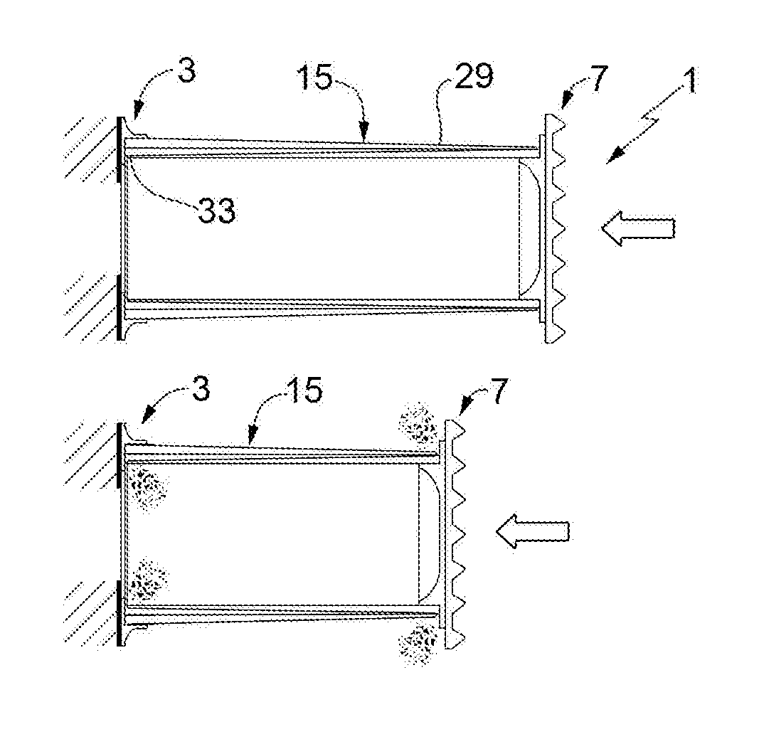
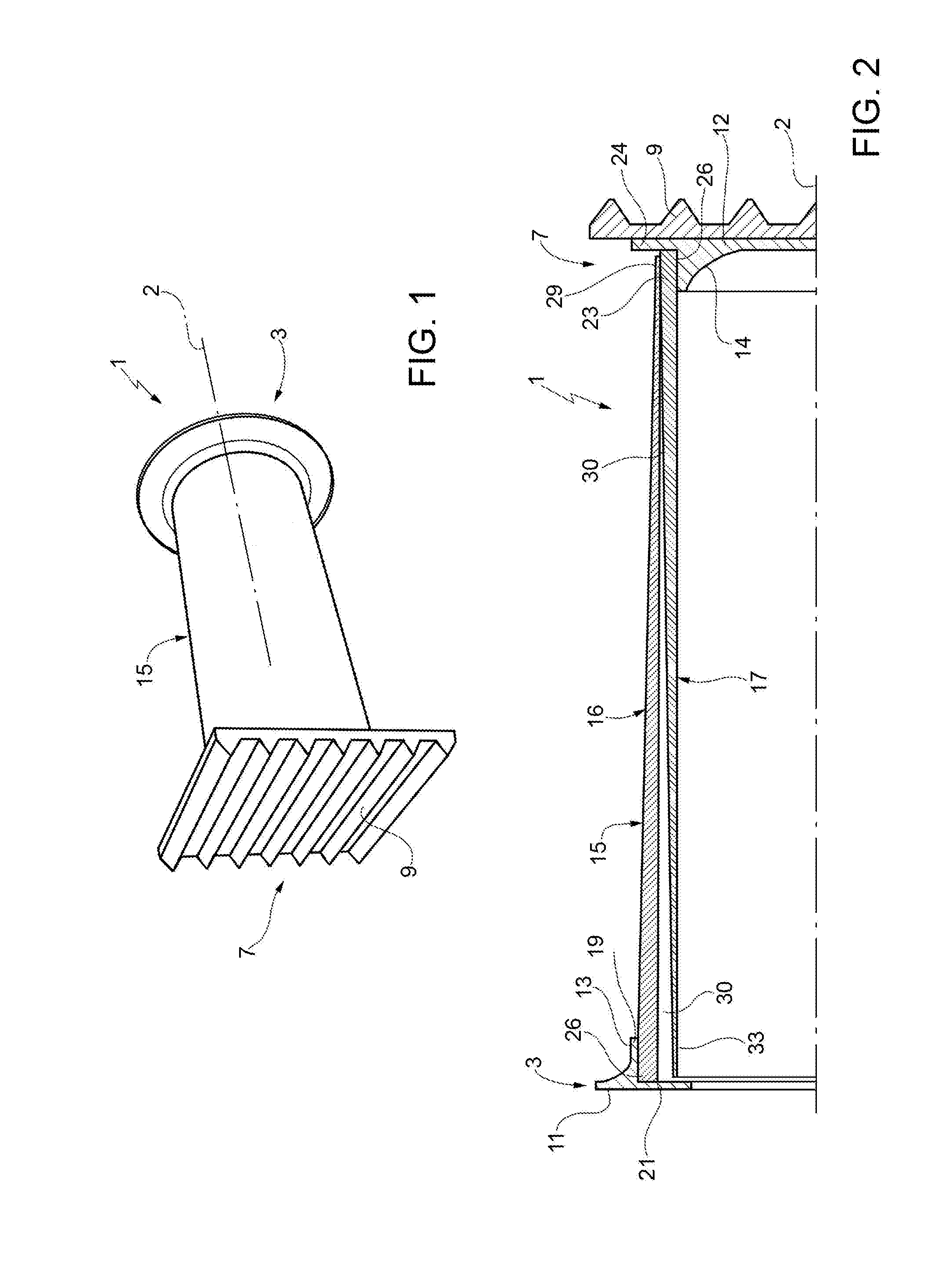
[0025]In FIG. 1, the reference number 1 designates an energy-absorbing device, which extends along an axis 2 and comprises, at an axial end thereof, an attachment member 3, which is designed to be fixed in a way known and not described in detail to a supporting structure of a vehicle, in particular of a rail-car (not illustrated).

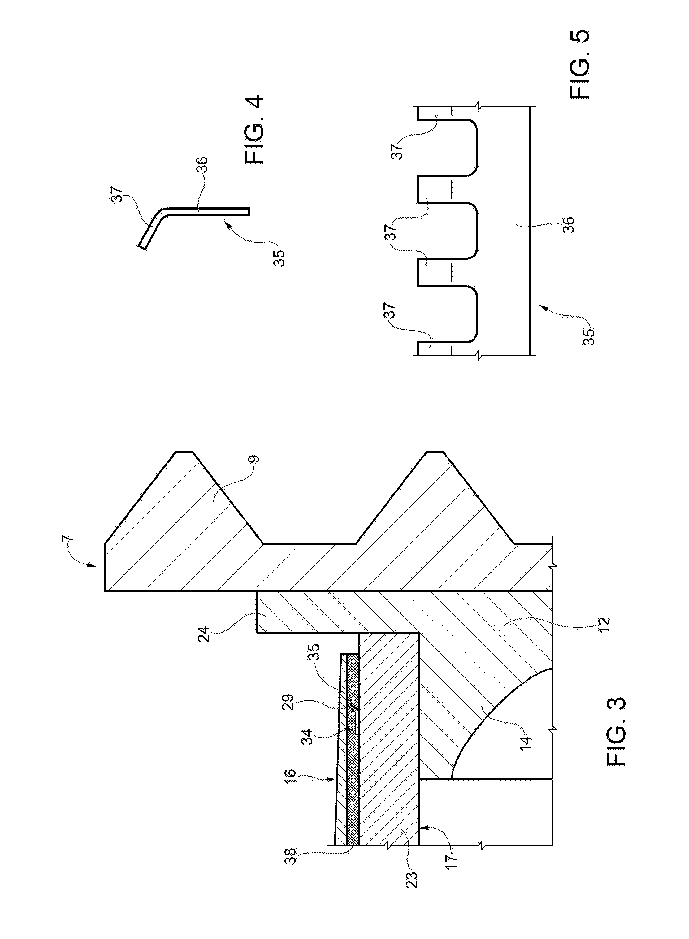
[0026]At the opposite axial end, the device 1 comprises an impact member 7 designed to withstand a head-on collision. Preferably, the member 7 terminates axially with an anti-climbing plate 9, which has a plurality of horizontal ribbings, or other equivalent elements, in order to perform an anti-climbing function when it impacts against a similar plate of another rail-car that forms part of the same train or else of another train.

[0027]The members 3, 7 are made of metal material, preferably aluminium alloy or steel. As may be seen in FIG. 2, in particular, the members 3, 7 comprise respective plane plates 11, 12 orthogonal to the axis 2, and respective coll...


PUM


Abstract

An energy-absorbing device, in particular for a rail-car, extends along an axis and has an attachment member, which can be connected to a fixed structure, an impact member, designed to withstand an impact, and an energy-absorbing member, constituted by a first tube and a second tube, which are coaxial and are made of composite material in order to collapse and hence absorb energy in the event of impact; the first tube is fixed to the attachment member, whereas the second tube is fixed to the impact member and is axially slidable, during impact, guided by the first tube; the radial thickness of the two tubes decreases along the axis, towards their free ends; in a non-collapsed resting condition, the axial gaps present between the two free ends and the attachment and impact members are substantially the same so that the two tubes start to collapse simultaneously in the event of impact.

Description

TECHNICAL FIELD[0001]The present invention relates to an energy-absorbing device, in particular for a rail-car.BACKGROUND ART[0002]As is known, rail-cars (powered railway carriage, coaches, etc.) of surface and underground trains have, at their ends, collapsible devices pre-arranged for absorbing energy in the event of head-on collision so as to safeguard the body that accommodates the passengers and / or drivers. In general, a collapsible device comprises a box-like body made of metal material coupled to an end plate, usually provided with anti-climbing ribbings. In the event of a head-on collision against said end plate, the box-like body undergoes plastic deformation and hence absorbs kinetic energy.[0003]Normally, during a head-on collision, the collapsible devices are not perfectly aligned with the ones against which they impact, but an offset in a vertical direction or else an angular offset is present between their axes. These offsets generate an asymmetrical distribution of th...

Claims


Application Information

Patent Timeline
Patent Type & Authority Applications(United States)
IPC IPC(8): B61G11/16B61G11/18
CPCB61G11/18B61G11/16
Inventor LENZI, LUCASURINI, ANGELOPACINI, SAMUELE
Owner HITACHI RAIL ITAL
Why Eureka
Try Eureka