Aftertreatment Module with Reduced Bypass Flow

a technology of bypass flow and aftertreatment bricks, which is applied in the direction of separation processes, machines/engines, mechanical equipment, etc., can solve the problems of potential leakage paths between adjacent catalytic members, depletion or deactivation of aftertreatment brick types, and damage to aftertreatment bricks

Active Publication Date: 2016-12-01
CATERPILLAR INC
View PDF1 Cites 12 Cited by
  • Summary
  • Abstract
  • Description
  • Claims
  • Application Information

AI Technical Summary

Problems solved by technology

However, some types of aftertreatment bricks may become depleted or deactivated after a period of use, or may become damaged due to the conditions in which th

Method used


Image

  • Aftertreatment Module with Reduced Bypass Flow
  • Aftertreatment Module with Reduced Bypass Flow
  • Aftertreatment Module with Reduced Bypass Flow

Examples


Embodiment Construction

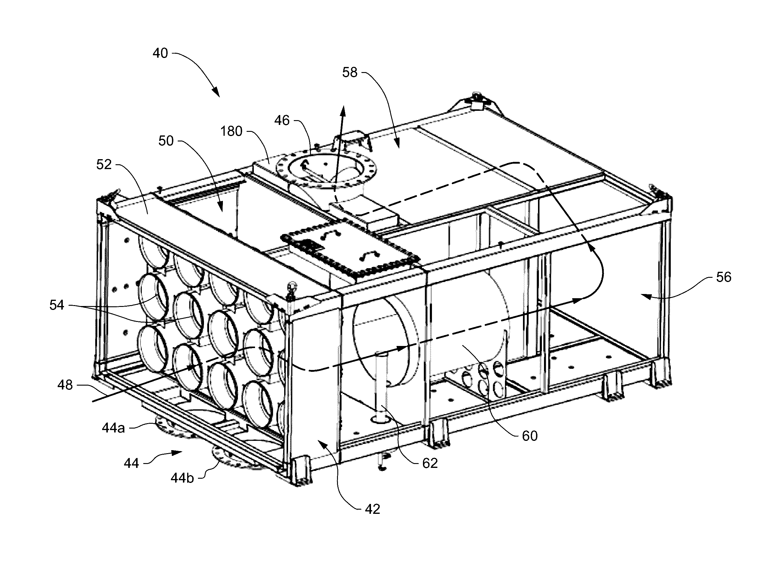
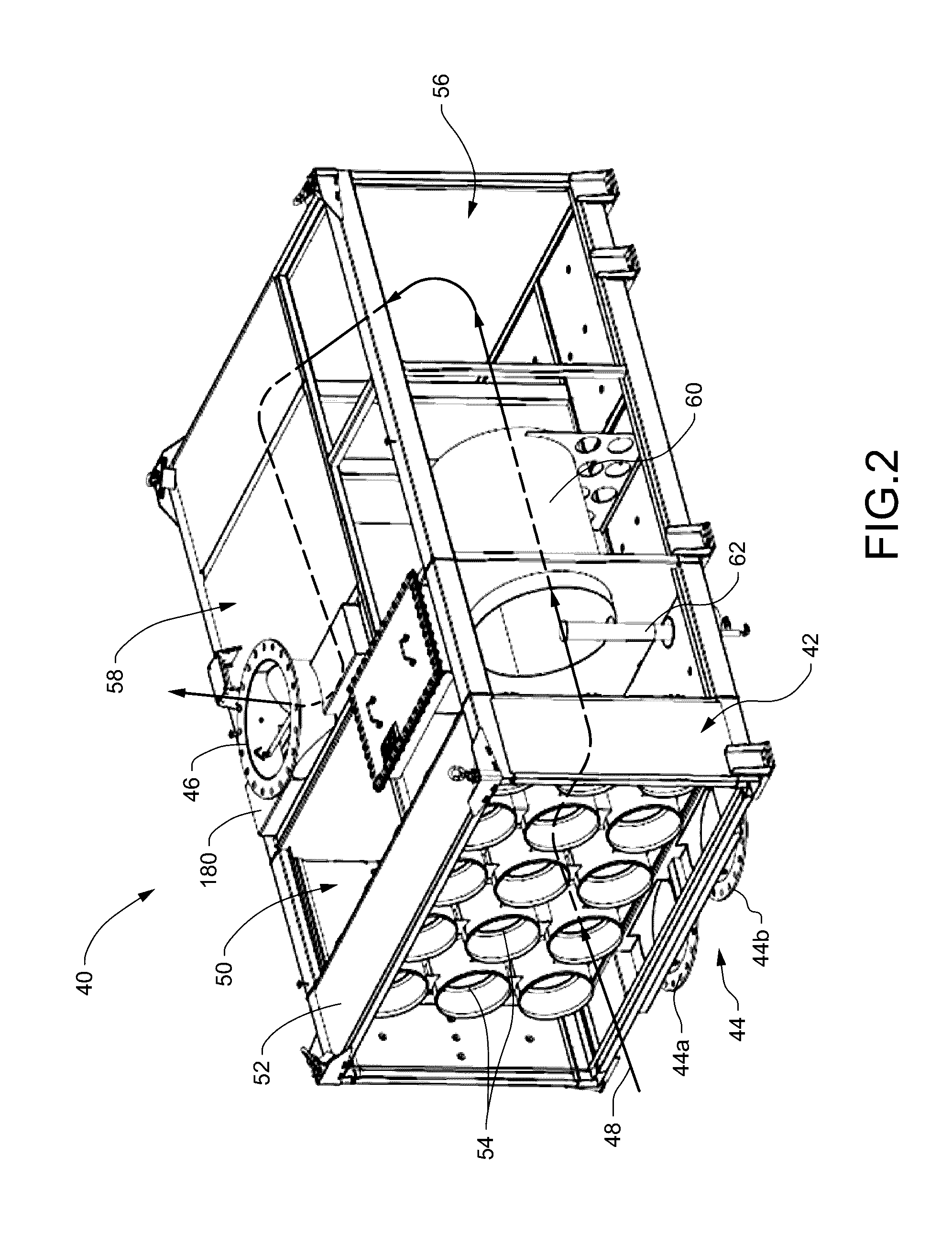
[0037]Embodiments of catalytic modules for use in aftertreatment systems, as well as catalytic bricks used in catalytic modules, are disclosed herein. The catalytic modules and bricks are configured to reduce the amount of exhaust gas leaking around the catalytic bricks. In some embodiments, the catalytic bricks include integral flanges extending across interfaces between adjacent catalytic bricks. In other embodiments, the catalytic module includes a frame having one or more flow modulators extending from the frame to the catalytic bricks.

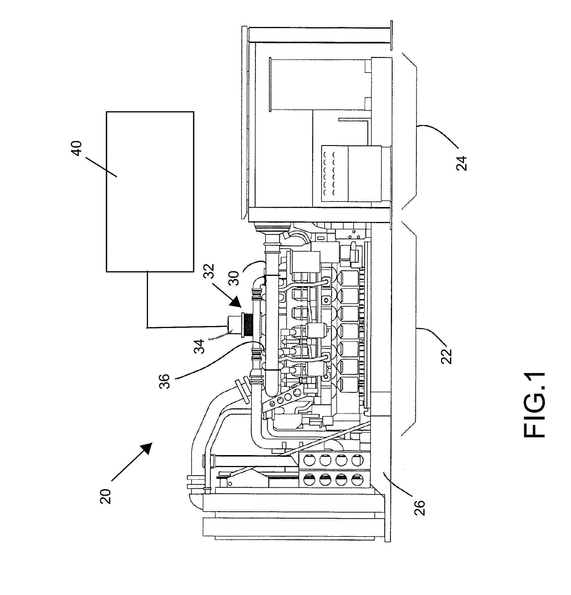
[0038]This disclosure relates generally to an exhaust aftertreatment system that may be associated with a power system producing exhaust gasses and, more particularly, relates to aftertreatment bricks that may be a removable component of such aftertreatment systems. FIG. 1 illustrates an exemplary power system 20 that can generate power by combusting fossil fuels or the like. The illustrated power system 20 may include an internal combustion engin...


PUM

PropertyMeasurementUnit
Flow rateaaaaaaaaaa
Shapeaaaaaaaaaa

Abstract

An aftertreatment module includes a catalytic brick having upstream and downstream flanges sized to extend over potential leak flow paths between bricks. Additionally, an aftertreatment module has an array of similarly flanged bricks to reduce leakage through all interfaces between adjacent bricks. A frame for holding the array of bricks includes flow modulators to restrict leakage through an interface between the frame and at least one side surface defined by the array of bricks.

Description

TECHNICAL FIELD[0001]The present disclosure generally relates to aftertreatment systems, and more particularly to reducing exhaust flow from bypassing catalytic modules used in aftertreatment systems.BACKGROUND[0002]Power systems such as large internal combustion engines, for example, burn hydrocarbon-based fuels or similar fuel sources to convert the chemical energy therein to mechanical energy for powering an associated machine or application. Combustion of the hydrocarbon fuel may release or create several byproducts or emissions, such as nitrogen oxides (NOX), carbon monoxides and carbon dioxides (CO and CO2), and particulate matter. The quantity of some of these emissions that may be released to the environment may be subject to government regulations and environmental laws. Accordingly, manufacturers of such power systems may equip the system with an associated aftertreatment system to treat the emissions before they are discharged to the environment.[0003]The aftertreatment s...

Claims


Application Information

Patent Timeline
IPC IPC(8): F01N3/20F01N3/28B01D53/94
CPCF01N3/2066F01N3/28B01D53/9431B01D53/9418B01D53/944B01D53/9472B01D2255/9035B01D2258/012B01D2258/018B01D2259/4566F01N3/2839F01N2450/02F01N2450/30F01N2590/10Y02T10/12
Inventor GARDUNO, JUAN A.DEASON, JAMESJUSTIN, JULIANRICHEY, R. ZACHARYDENG, LINGPELTIER, JAMES D.
Owner CATERPILLAR INC
Why Eureka
Try Eureka