Power module

Active Publication Date: 2016-12-01
DELTA ELECTRONICS INTL SINGAPORE
View PDF5 Cites 12 Cited by
  • Summary
  • Abstract
  • Description
  • Claims
  • Application Information

AI Technical Summary

Benefits of technology

[0007]An object of the present invention provides a power module with semiconductor switches and diodes embedded within insulation layers. Consequently, a first sub-module and a second sub-module are formed as a high-voltage-side switching element and a low-voltage-side switching element of a bridge circuit. The high-voltage-side switching element and the low-voltage-side switching element are disposed on a substrate and electrically

Problems solved by technology

However, since the high-voltage-side switching elements and the low-voltage-side switching elements are connected with each other by the wire-bonded technology, some drawbacks occur.
For example, the long wires for connecting the high-voltage-side switching elements and the low-voltage-side switching elements may increase the parasitic inductance between the wires and the substrate.
Under this circumstance, the switching efficiency of the high-voltage-side switching elements and the low-voltage-side switching elements will be adversely affected.
Moreover, since the long wire has a large impedance value, the power conversion efficiency is impaired.
Moreover, the side of the substrate for

Method used


Image

  • Power module
  • Power module
  • Power module

Examples


Embodiment Construction

[0015]The present invention will now be described more specifically with reference to the following embodiments. It is to be noted that the following descriptions of preferred embodiments of this invention are presented herein for purpose of illustration and description only. It is not intended to be exhaustive or to be limited to the precise form disclosed.

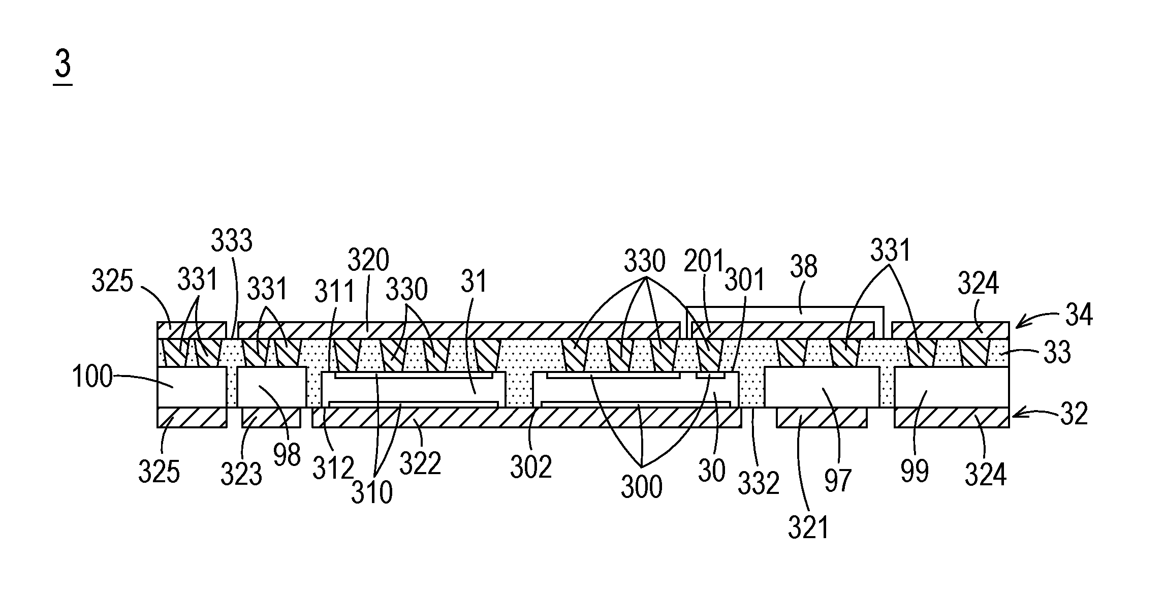
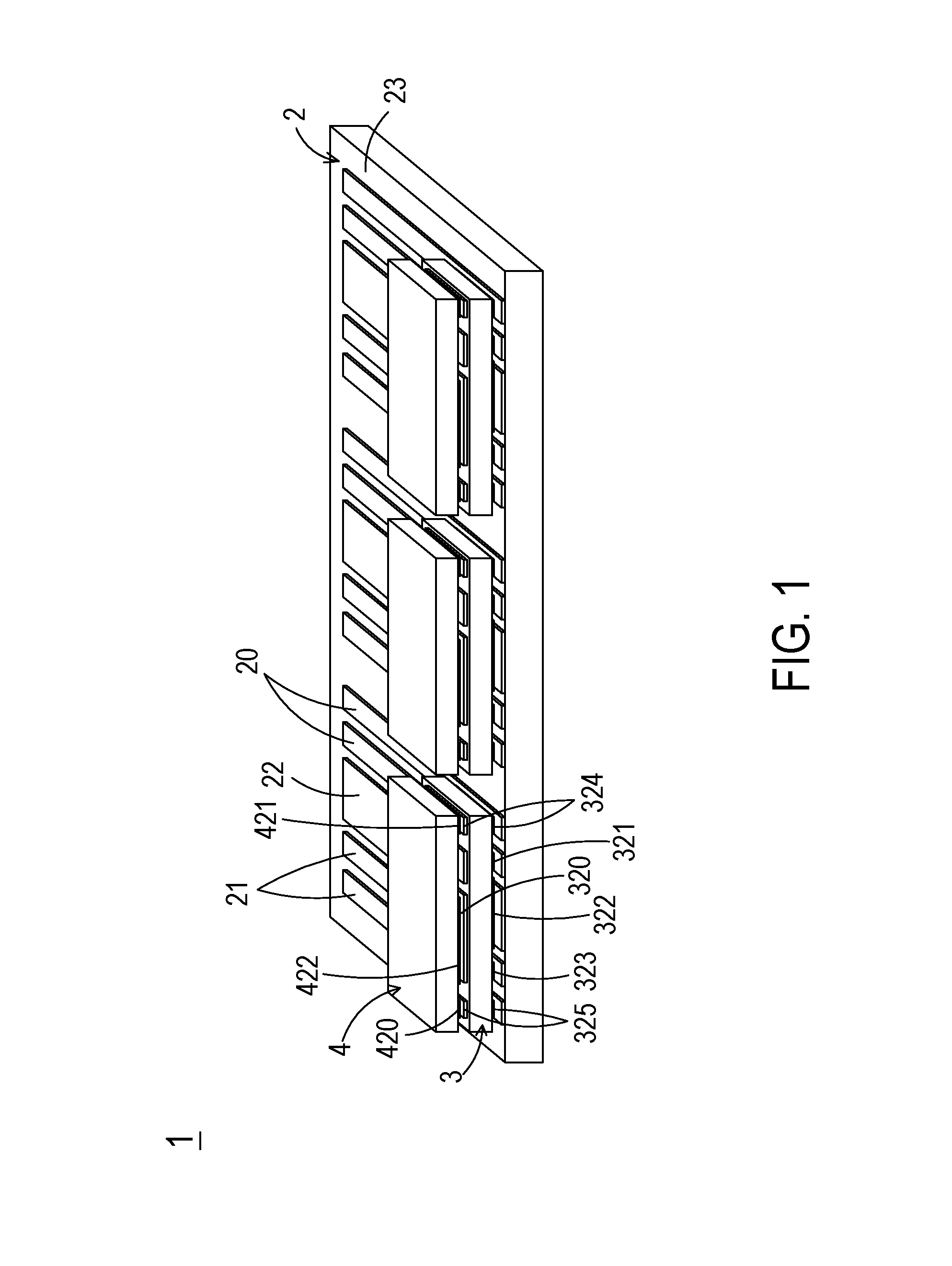
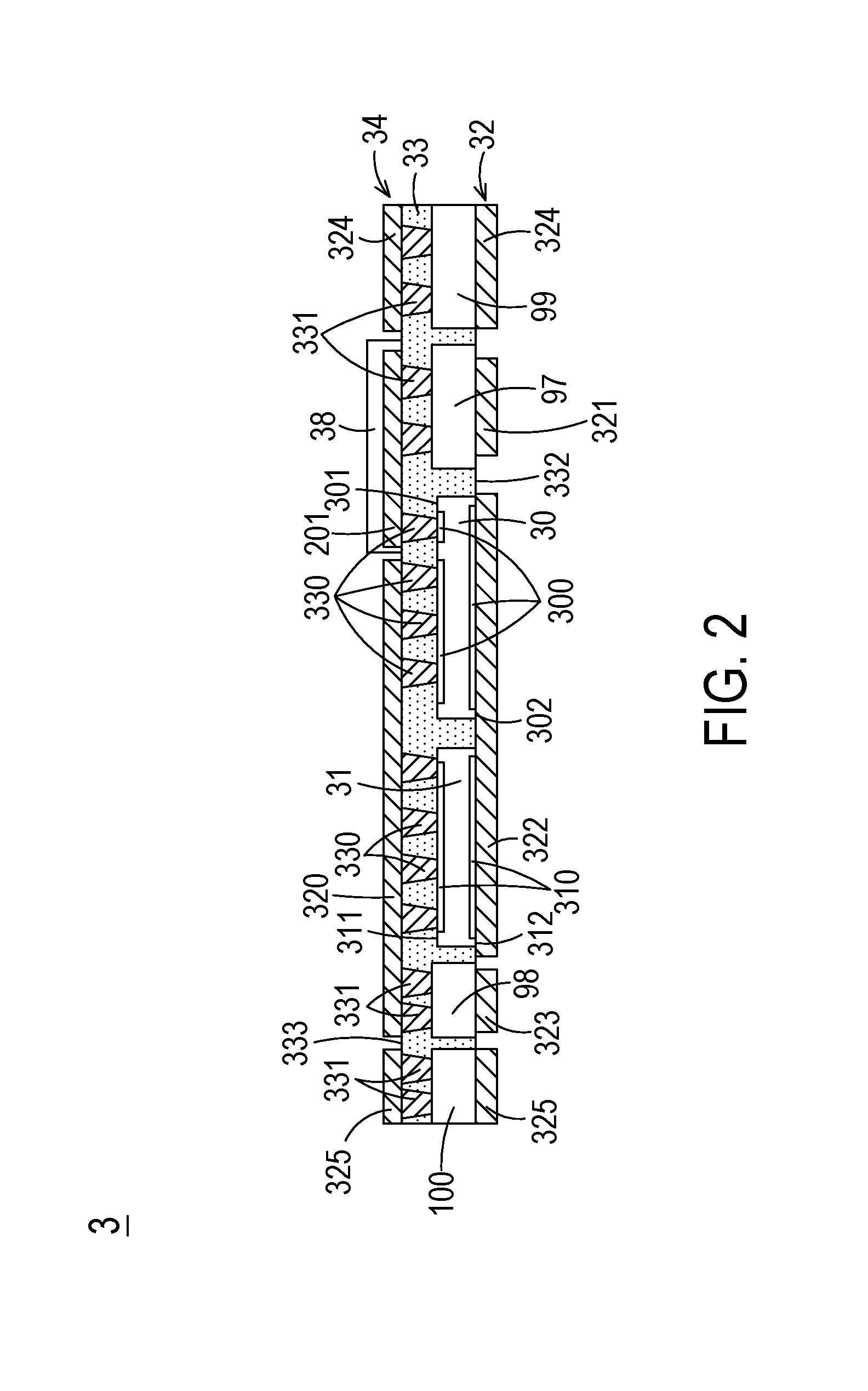
[0016]FIG. 1 is a schematic perspective view illustrating a power module according to an embodiment of the present invention. FIG. 2 is a schematic cross-sectional view illustrating a first sub-module of the power module of FIG. 1. FIG. 3 is a schematic cross-sectional view illustrating a second sub-module of the power module of FIG. 1. Please refer to FIGS. 1, 2 and 3. The power module 1 comprises a substrate 2, at least one first sub-module 3 and at least one second sub-module 4. Moreover, plural first conducting parts 20, plural second conducting parts 21 and at least one third conducting part 22 are formed on a first surface ...


PUM


Abstract

A power module includes a substrate, a first sub-module and a second sub-module. Each of the first sub-module and the second sub-module includes a semiconductor switch and a diode. The first sub-module is formed as the high-voltage-side switching element. The second sub-module is formed as the low-voltage-side switching element. The plural electrodes of the high-voltage-side switching element and the plural electrodes of the low-voltage-side switching element are electrically connected with the conducting terminals of the corresponding semiconductor switches and the corresponding diodes. The high-voltage-side switching element is disposed on the substrate and electrically connected with the corresponding conducting parts of the substrate. The low-voltage-side switching element is disposed on the high-voltage-side switching element and electrically connected with the corresponding conducting parts of the substrate through the high-voltage-side switching element.

Description

FIELD OF THE INVENTION[0001]The present invention relates to a power module, and more particularly to a power module for a power converter.BACKGROUND OF THE INVENTION[0002]Recently, the general trends in designing power converters are toward high efficiency and high density. The high efficiency power converter can reduce the power loss and achieve the power-saving purpose. The high density power converter can reduce the overall volume of the electronic product and meet the requirements of small size and light weightiness.[0003]Generally, a power converter comprises a bridge circuit for rectification. The bridge circuit comprises at least one high-voltage-side switching element and at least one low-voltage-side switching element. For example, a three-phase bridge circuit of a three-phase power converter comprises three high-voltage-side switching elements and three low-voltage-side switching elements. The high-voltage-side switching elements are connected with the corresponding low-v...

Claims


Application Information

Patent Timeline
IPC IPC(8): H01L23/495H02M7/06H01L23/31H02M7/219H01L29/739H01L29/861
CPCH01L23/49562H01L29/7395H01L29/861H02M7/06H01L23/49568H01L23/3114H02M7/219H01L23/49575H02M1/00H01L23/5389H01L25/112H01L25/18H02M7/003H01L23/3735H01L23/49861H01L23/5384H02M7/5387H01L2224/04105H01L2224/06181H01L2224/24137H01L2224/2518H05K1/185H01L24/20H05K1/141H05K1/144H05K1/0262H01L2924/13055H01L24/18
Inventor LAI, YIU-WAICHEN, DA-JUNG
Owner DELTA ELECTRONICS INTL SINGAPORE
Why Eureka
Try Eureka