
Energy storage device and energy storage apparatus

Active Publication Date: 2016-12-01
GS YUASA INT LTD
View PDF7 Cites 3 Cited by
  • Summary
  • Abstract
  • Description
  • Claims
  • Application Information

AI Technical Summary

Benefits of technology

The invention is aimed at improving the input performance of an energy storage device while preventing its cycle performance from declining.

Problems solved by technology

The graphite has a high capacity and is excellent in potential flatness; however, absorption / desorption performance of lithium ions is deteriorated when repeating charge-discharge.
On the other hand, the non-graphitizable carbon has a smaller capacity and a lower power potential at a low SOC region than the graphite; however, absorption / desorption performance of lithium ions is hardly deteriorated when repeating charge-discharge.
However, it is difficult to adequately improve the input performance of the secondary battery even by the conventional technology, and so it has been thought to improve input performance by reducing a particle size of a negative active material.
However, the cycle performance may be deteriorated when the particle size of the graphite and the particle size of the non-graphitizable carbon are simply decreased.

Method used


Image

  • Energy storage device and energy storage apparatus
  • Energy storage device and energy storage apparatus
  • Energy storage device and energy storage apparatus

Examples


embodiment 1

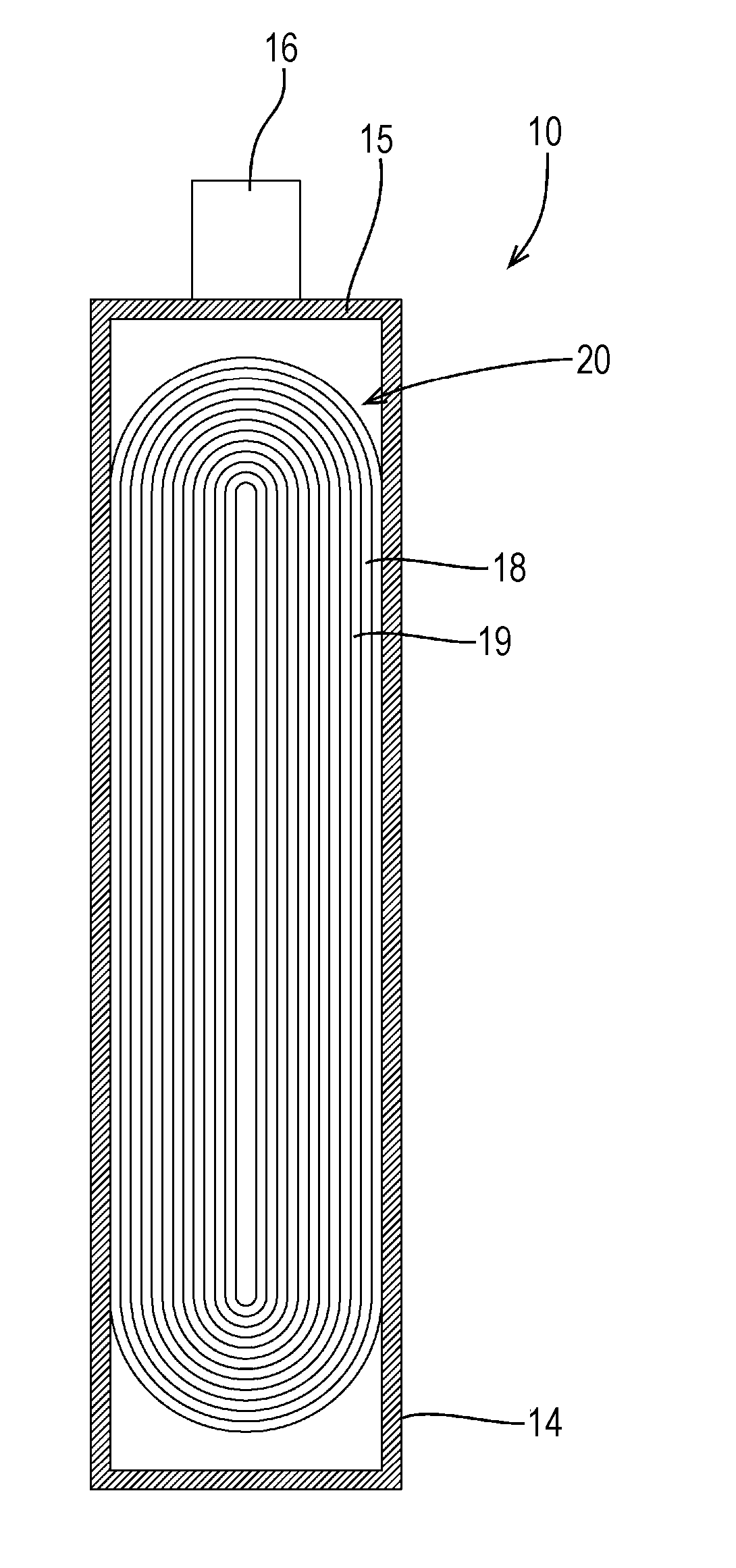
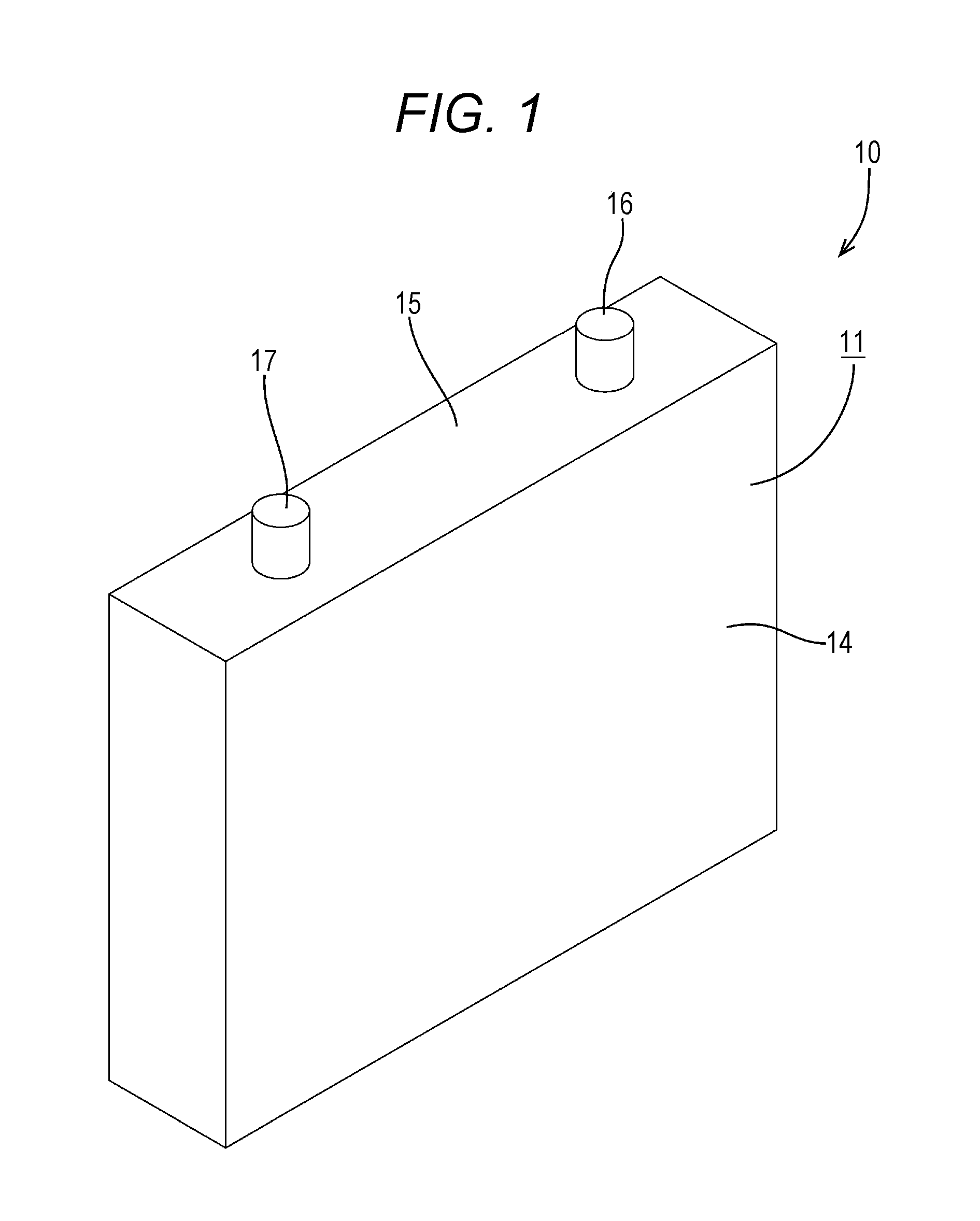
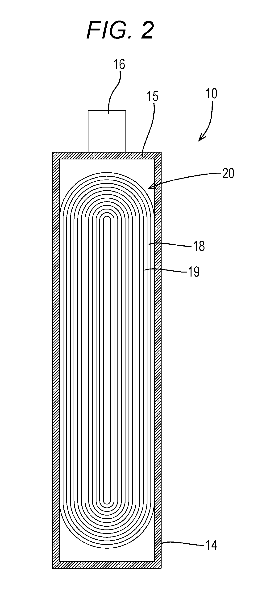
[0044]Hereinafter, Embodiment 1 will be described with reference to FIG. 1 to FIG. 14. An energy storage device 10 of Embodiment 1 is mounted on vehicles (not shown) such as electric vehicles and hybrid automobiles, and used as a power source. The energy storage device 10 of Embodiment 1 is a lithium ion battery and formed by housing an electrode group 20 in a case 11. The electrode group 20 includes a positive electrode plate (corresponding to a positive electrode) 18, a negative electrode plate (corresponding to a negative electrode) 19, a separator, and an electrolyte solution (not shown). Incidentally, the energy storage device 10 is not limited to a lithium ion battery, and an optional storage battery can be selected as required.

[0045]As shown in FIG. 1, the case 11 has a flat rectangular parallelepiped shape. The case 11 may be made of metal, or may be made of a synthetic resin. As the metal constituting the case 11, as required, an optional metal of iron, an iron alloy, alumi...


PUM


Abstract

An energy storage device includes a positive electrode and a negative electrode. The negative electrode includes graphite and non-graphitizable carbon, and a D50 particle size of the graphite at which a cumulative volume in a particle size distribution of a particle size reaches 50% is 2 μm or more. A ratio of a mass of the non-graphitizable carbon to a total amount of a mass of the graphite and a mass of the non-graphitizable carbon is 5% by mass or more and 45% by mass or less and a ratio of the D50 particle size of the graphite to a D50 particle size of the non-graphitizable carbon is 1.02 or less.

Description

CROSS-REFERENCE TO RELATED APPLICATIONS[0001]This application is based on Japanese Patent Application No. 2015-110296 filed on May 29, 2015, the entire contents of which are hereby incorporated by reference.FIELD[0002]A technology described in the present specification relates to an energy storage device and an energy storage apparatus.BACKGROUND[0003]Heretofore, an energy storage device described in JP-A-11-250909 is known, for example. This energy storage device includes a positive electrode, and a negative electrode capable of absorbing / desorbing lithium ions. The negative electrode has a negative active material containing a composite carbon material including graphite and non-graphitizable carbon.[0004]The graphite has a high capacity and is excellent in potential flatness; however, absorption / desorption performance of lithium ions is deteriorated when repeating charge-discharge. On the other hand, the non-graphitizable carbon has a smaller capacity and a lower power potential ...

Claims


Application Information

Patent Timeline
IPC IPC(8): H01M10/0587H01M4/62H01M4/587H01M10/0525H01M4/133
CPCH01M10/0587H01M10/0525H01M2004/027H01M4/587H01M4/625H01M4/133H01M4/583H01G11/24H01G11/32H01G11/38H01M4/364H01M4/622H01M10/647Y02E60/10Y02P70/50Y02E60/13
Inventor KAKO, TOMONORIYAMAFUKU, TAROMIYAZAKI, AKIHIKO
Owner GS YUASA INT LTD
Learn More