
Rainout control in a pressure support system

Active Publication Date: 2016-12-08
KONINKLJIJKE PHILIPS NV
View PDF7 Cites 10 Cited by
  • Summary
  • Abstract
  • Description
  • Claims
  • Application Information

AI Technical Summary

Benefits of technology

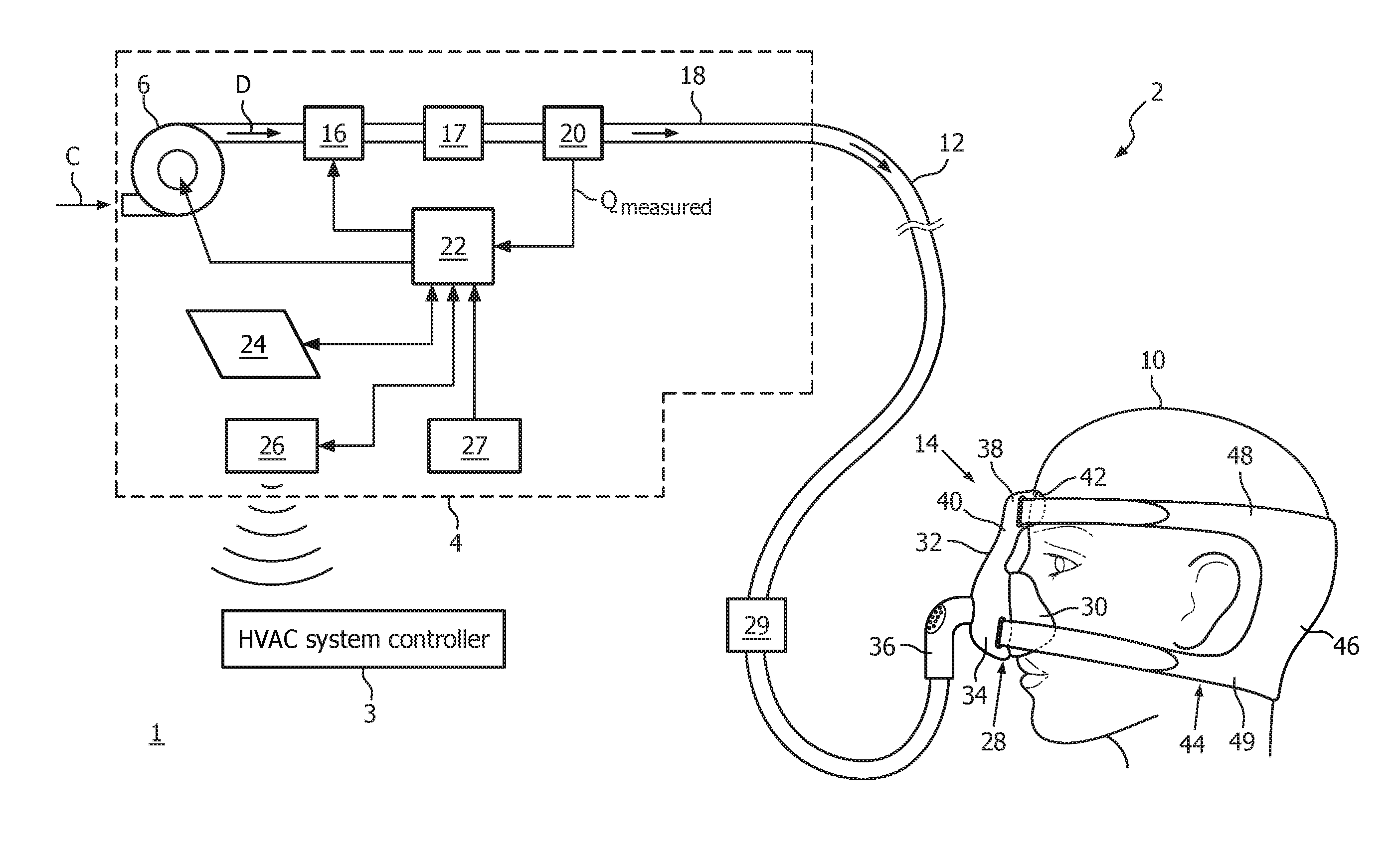
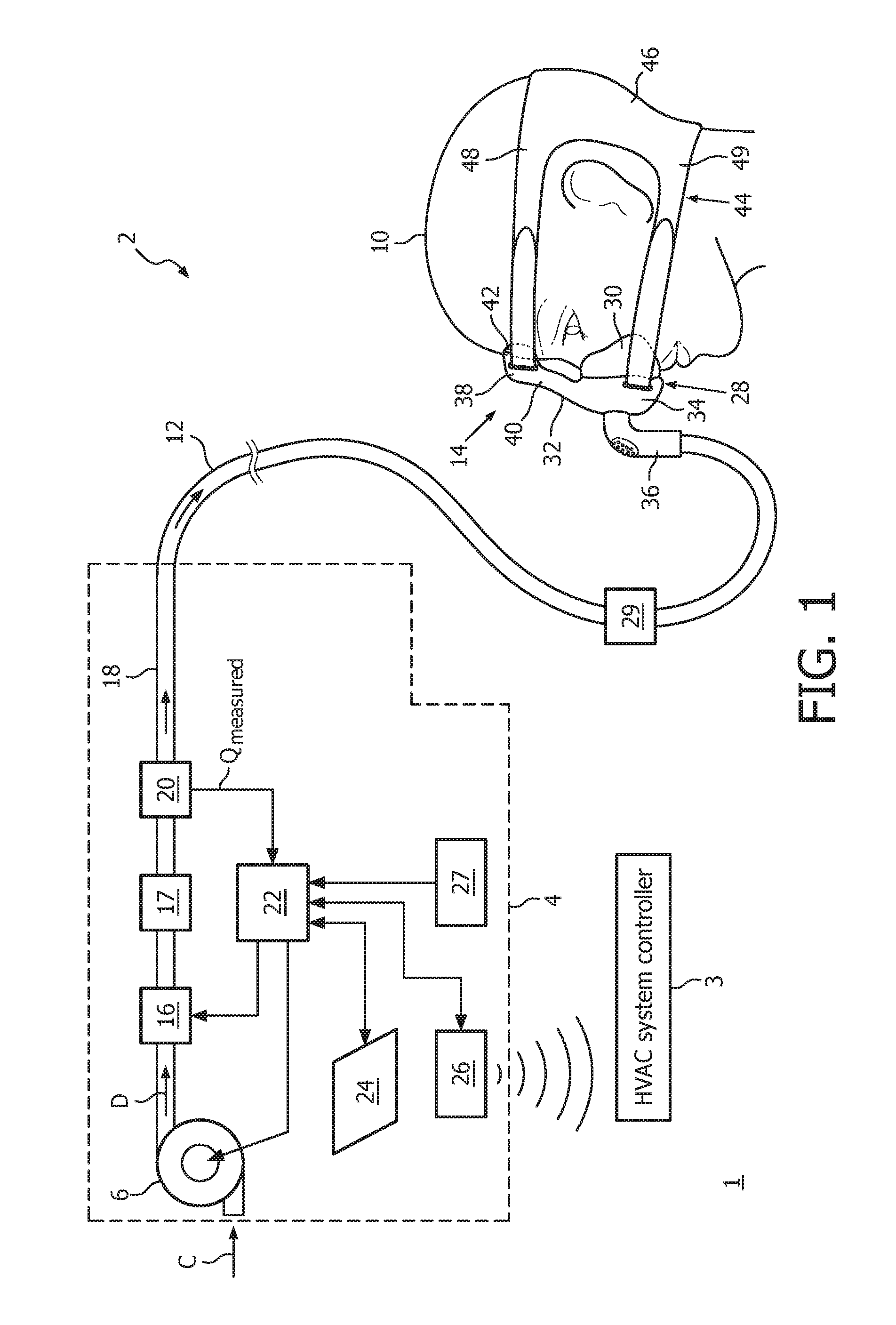
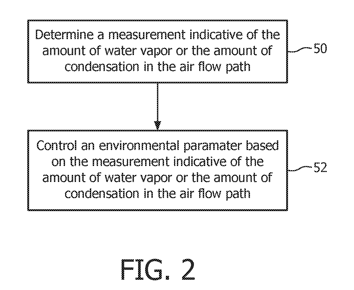
The present invention is a pressure support device that overcomes the shortcomings of conventional devices. The device includes a pressure generating device, an airflow path, and a control system. The control system stores and executes several routines to determine the amount of water vapor or condensation in the airflow path and generate control signals to adjust the environmental parameters to reduce the likelihood of rainout in the airflow path. These control signals are transmitted to an environmental control device to control the external environment. The technical effect of the invention is to prevent rainout in the pressure support device, which can cause damage and discomfort to patients.

Problems solved by technology

Those afflicted with sleep apnea experience sleep fragmentation and complete or nearly complete cessation of ventilation intermittently during sleep with potentially severe degrees of oxyhemoglobin desaturation.
Sleep apnea sufferers may be at risk for excessive mortality from these factors as well as by an elevated risk for accidents while driving and / or operating potentially dangerous equipment.
Even if a patient does not suffer from a complete or nearly complete obstruction of the airway, it is also known that adverse effects, such as arousals from sleep, can occur where there is only a partial obstruction of the airway.
Partial obstruction of the airway typically results in shallow breathing referred to as a hypopnea.
When rainout occurs, it often disturbs the patient, which in turn may cause the patient to discontinue therapy for the remainder of the night.
The temperature of the air within the airflow circuit decreases when it makes contact with the walls of the circuit, resulting in condensation (i.e. “rainout”).
Some pressure support systems attempt to reduce rainout by adding heating elements to the walls of the airflow circuit (e.g. a heated hose), but this is only a partial solution since it is impractical to add heating elements to all of the surfaces of the airflow circuit.
Also, the addition of heating elements and associated electronics is expensive and adds additional weight to the system (especially important for wearable components).

Method used


Image

  • Rainout control in a pressure support system
  • Rainout control in a pressure support system
  • Rainout control in a pressure support system

Examples


Embodiment Construction

[0020]As used herein, the singular form of “a”, “an”, and “the” include plural references unless the context clearly dictates otherwise. As used herein, the statement that two or more parts or components are “coupled” shall mean that the parts are joined or operate together either directly or indirectly, i.e., through one or more intermediate parts or components, so long as a link occurs. As used herein, “directly coupled” means that two elements are directly in contact with each other. As used herein, “fixedly coupled” or “fixed” means that two components are coupled so as to move as one while maintaining a constant orientation relative to each other.

[0021]As used herein, the word “unitary” means a component is created as a single piece or unit. That is, a component that includes pieces that are created separately and then coupled together as a unit is not a “unitary” component or body. As used herein, the statement that two or more parts or components “engage” one another shall me...


PUM


Abstract

A pressure support system includes a pressure generating device, an airflow path, and a control system. The control system is structured to determine a first measurement indicative of an amount of water vapor in the airflow path or an amount of condensation in the airflow path and generate a number of control signals structured to control an environmental control device structured to control an environmental parameter in an environment including the pressure support system, wherein the control signals are generated based on at least the first measurement and are configured to cause the environmental control device to adjust the environmental parameter in a manner that will reduce a degree or a likelihood of rainout in the airflow path, and transmit the control signals to the environmental control device so that it may be controlled to reduce the degree or likelihood of rainout.

Description

CROSS-REFERENCE TO RELATED APPLICATIONS[0001]This patent application claims the priority benefit under 35 U.S.C. §119(e) of U.S. Provisional Application No. 62 / 170,301, filed on Jun. 3, 2015, the contents of which are herein incorporated by reference.BACKGROUND OF THE INVENTION[0002]1. Field of the Invention[0003]The present invention pertains to airway pressure support devices, and, in particular, to a system and method for monitoring and controlling the degree of rainout in a pressure support device by automatically controlling a parameter affecting rainout, such as one or more environmental conditions.[0004]2. Description of the Related Art[0005]Many individuals suffer from disordered breathing during sleep. Sleep apnea is a common example of such sleep disordered breathing suffered by millions of people throughout the world. One type of sleep apnea is obstructive sleep apnea (OSA), which is a condition in which sleep is repeatedly interrupted by an inability to breathe due to an...

Claims


Application Information

Patent Timeline
IPC IPC(8): A61M16/00A61M16/20F24F11/02A61M16/06F24F11/00F24F11/08A61M16/08A61M16/16
CPCA61M16/0066F24F2011/0091A61M16/20A61M16/16A61M16/0666A61M16/0683F24F11/0012F24F11/0015F24F11/006F24F11/08F24F11/022A61M2205/3327A61M2205/50A61M2205/3368A61M2205/3584A61M2016/0027A61M2230/40A61M2205/502F24F2013/221F24F2011/0068A61M16/0875A61M2205/3561A61M2205/3592A61M16/161A61M16/024F24F11/30F24F2110/20F24F11/80
Inventor GRASHOW, JONATHAN SAYER
Owner KONINKLJIJKE PHILIPS NV
Learn More