Manufacturing method, golf club head, and design method

a golf club head and manufacturing method technology, applied in the field of wood-type golf club heads, can solve the problems of small spin amount of the shot, and it is difficult for the golfer to intentionally bend the shot to the left or righ

Inactive Publication Date: 2016-12-08
BRIDGESTONE SPORTS
View PDF50 Cites 15 Cited by
  • Summary
  • Abstract
  • Description
  • Claims
  • Application Information

AI Technical Summary

Benefits of technology

[0008]According to an aspect of the present invention it is provided a method of manufacturing a wood type golf club head including a face portion, a crown portion, and a sole portion, comprising: a setting step of setting a surface roughness of the face portion; and a step of forming the face portion based on the surface roughness set in the setting step, wherein in the setting step, the larger a moment of inertia of the golf club head is, the larger the surface roughness outside an impact area of the face portion is set, and the smaller the moment of inertia is, the smaller the surface roughness outside the impact area of the face portion is set.

Problems solved by technology

However, in a golf club head having a relatively small loft angle (for example, 20° or less), the larger the surface roughness of the face is, the smaller the spin amount of a shot tends to be.
However, if the spin amount of a shot is small, and it is difficult for the golfer to intentionally bend the shot to the left or right.
This is disadvantageous from the viewpoint of shot control.

Method used


Image

  • Manufacturing method, golf club head, and design method
  • Manufacturing method, golf club head, and design method
  • Manufacturing method, golf club head, and design method

Examples


first embodiment

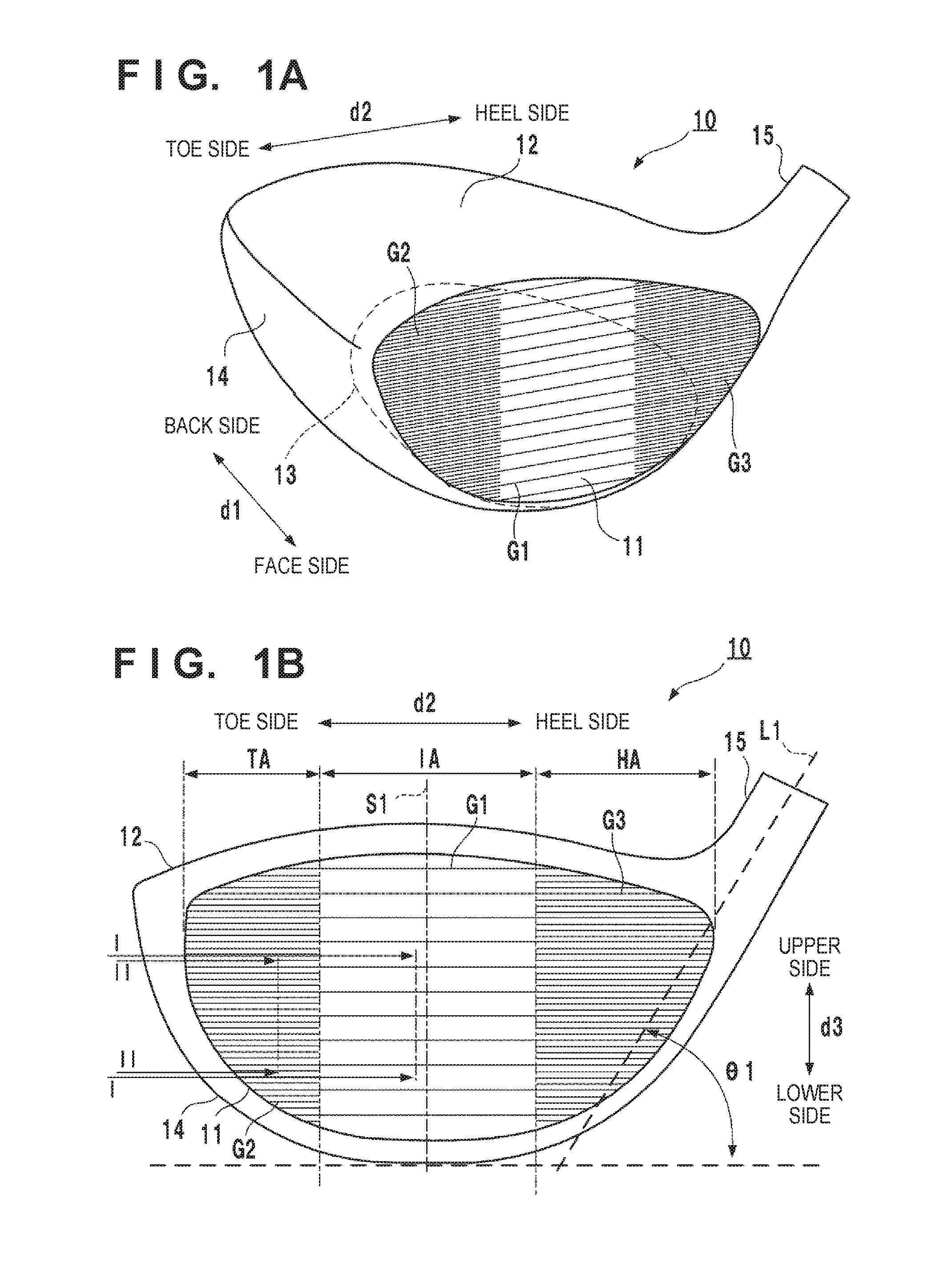
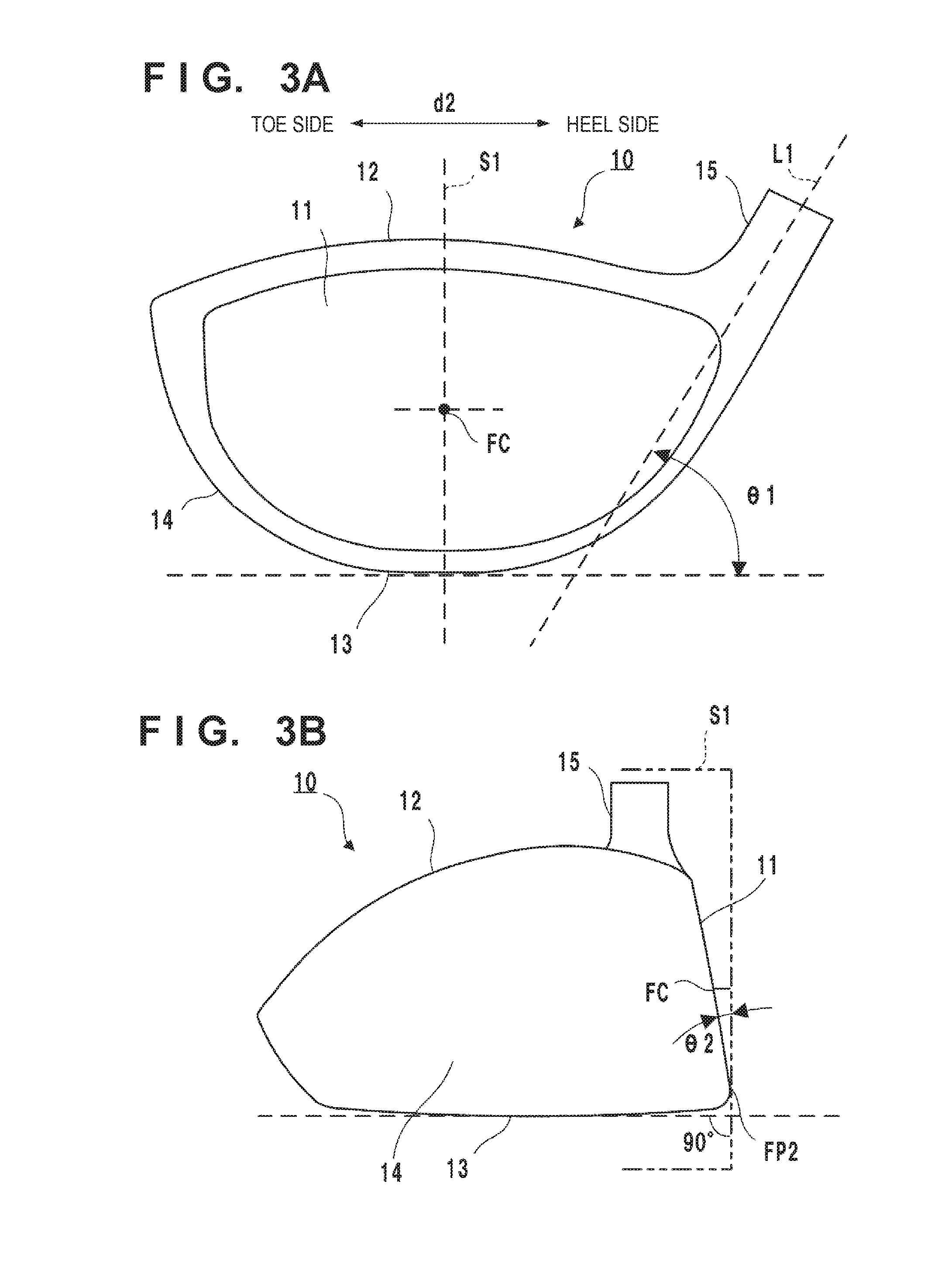
[0022]FIG. 1A is a perspective view of a golf club head 10 according to an embodiment of the present invention. FIG. 1B is a front view showing the golf club head 10 viewed from the side of a face portion 11.

[0023]The golf club head 10 forms a hollow member. Its peripheral walls form the face portion 11, a crown portion 12, a sole portion 13, and a side portion 14. The surface of the face portion 11 forms a face (striking face). A bulge and a roll are formed on the face. The crown portion 12 forms the upper portion of the golf club head 10. The sole portion 13 forms the bottom portion of the golf club head 10. The side portion 14 forms the portion between the sole portion 13 and the crown portion 12. The golf club head 10 also includes a hosel portion 15 to which a shaft is attached.

[0024]An arrow d1 in FIG. 1A indicates a face-back direction, and an arrow d2 indicates a toe-heel direction. An arrow d3 in FIG. 1B indicates the vertical direction of the face portion 11. The face-back...

second embodiment

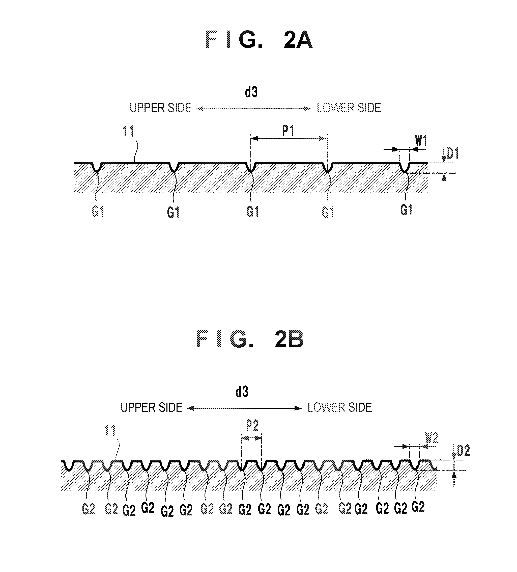
[0067]Score lines can be formed in a face portion 11 in addition to shallow grooves G. FIG. 5B shows an example. In the example of FIG. 5B, score lines 20 are formed in areas TA and HA other than an impact area IA. The score lines 20 are straight grooves extending in the toe-heel direction and are formed in parallel to each other.

[0068]The score lines 20 may be formed in the impact area IA as well. A structure without the score lines 20 in the areas TA and HA other than the impact area IA can also be employed.

third embodiment

[0069]In the first embodiment, the shallow grooves G have been explained as straight grooves. However, shallow grooves G may be grooves having another shape. FIGS. 6A to 6D show examples. FIGS. 6A and 6B show examples of the shallow grooves G having wavy shapes. FIG. 6A shows a case in which the shallow grooves G are formed into a triangular wave shape, and FIG. 6B shows a case in which the shallow grooves G are formed into a sine wave shape. FIG. 6C shows an example in which the shallow grooves G are grooves having an arc shape. FIG. 6D shows an example in which shallow grooves Ga having a triangular wave shape and shallow grooves Gb having a sine wave shape are repetitively formed. As in this example, the shallow grooves G may be formed by periodically forming grooves having different shapes.

[0070]In the first embodiment, the shallow grooves G are formed so as to be level when the golf club head 10 is grounded toward the target direction. However, the shallow grooves G need not be...


PUM


Abstract

The present invention relates to a method of manufacturing a wood type golf club head including a face portion, a crown portion, and a sole portion. The method includes a setting step of setting a surface roughness of the face portion and a step of forming the face portion based on the surface roughness set in the setting step. In the setting step, the larger a moment of inertia of the golf club head is, the larger the surface roughness outside an impact area of the face portion is set, and the smaller the moment of inertia is, the smaller the surface roughness outside the impact area of the face portion is set.

Description

BACKGROUND OF THE INVENTION[0001]Field of the Invention[0002]The present invention relates to a wood type golf club head.[0003]Description of the Related Art[0004]In a golf club head having a relatively large loft angle, the larger the surface roughness of the face portion is, the larger the spin amount of a shot tends to be. However, in a golf club head having a relatively small loft angle (for example, 20° or less), the larger the surface roughness of the face is, the smaller the spin amount of a shot tends to be. Japanese Patent Laid-Open No. 2008-79969 and 2004-222905 propose golf club heads with a focus on this point.[0005]In a golf club head, generally, the position of a hit on the face portion may degrade the carry or spin amount of a shot. To improve this, each of Japanese Patent Laid-Open No. 2004-222905, 5-237206, and 62-144674, Japanese Utility Model Laid-Open No. 3-16963, U.S. Patent Application Publication No. 2012 / 0052980, and U.S. Pat. No. 6,309,310 discloses a golf c...

Claims


Application Information

Patent Timeline
Patent Type & Authority Applications(United States)
IPC IPC(8): A63B53/04
CPCA63B53/0466A63B53/0408A63B53/0445
Inventor BAN, WATARU
Owner BRIDGESTONE SPORTS
Why Eureka
Try Eureka