
Eureka
For R&D, Eureka makes reading and utilizing patents & technical documents easy.
Eureka AIR
Designed for self-driven R&D workflows. Generate viable solutions, solve complex R&D challenges, empower your innovation with AI.

Eureka Materials
Designed for material experts only. Revolutionize your material R&D, from search, analyze, to developing new materials.

TechResearch
Generate reliable direction feasibility study reports for your R&D in just a few steps.

TechSeek
Discover and master advanced knowledge NOW. Basics, ideas, possibilities, all at once.

TechMind
As an expert in R&D Theories, TechMind can generates customized viable solutions instantly.

TechRisk
Analyze your overall solution with one click, know your potential R&D risks in advance.

TechMonitor
Get weekly tech updates, stay abreast of the latest tech innovations and key insights.
Method for manufacturing liquid ejection head
- Summary
- Abstract
- Description
- Claims
- Application Information
AI Technical Summary
Benefits of technology
Problems solved by technology
Method used
Image

Examples
first embodiment
[0056]The process in a first embodiment of the present invention will be described with reference to FIG. 5. (a), (b) and (c) in FIG. 5 are flowcharts illustrating the process for joining a plurality of element substrates C to the support plate 1 in the method for manufacturing a liquid ejection head according to the present embodiment.
[0057]First, an adhesive application step S1 of (a) in FIG. 5, which is the first step, will be described with reference to FIG. 6. The adhesive application of step S1 is an example of a first application step.
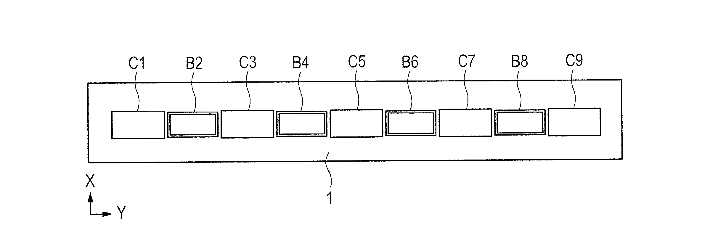
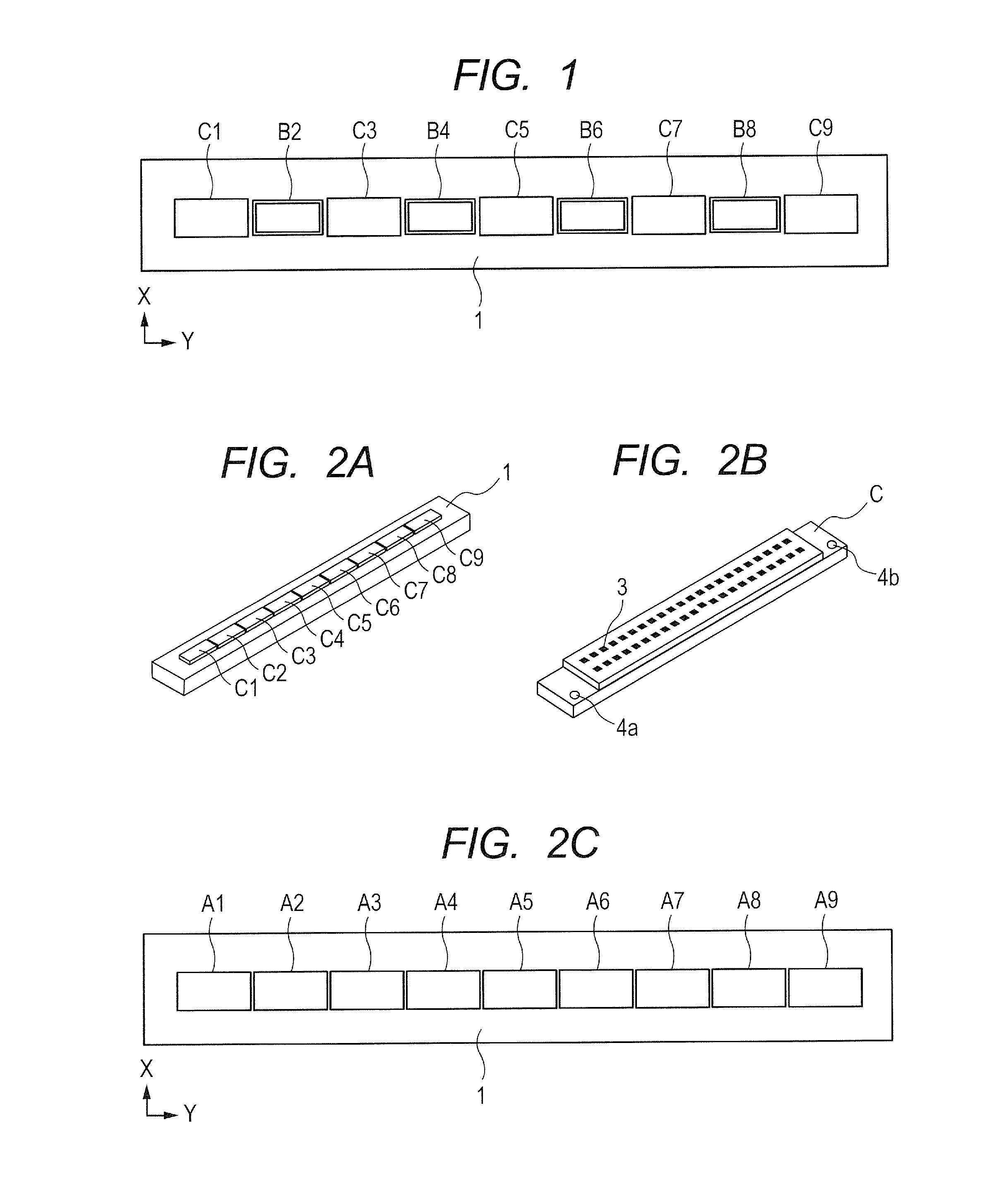
[0058]In step S1, an application device (not illustrated) is used to apply a UV adhesive to the support plate 1 at the positions where the element substrates C are to be joined. The adhesive has to be applied in a shape that matches the element substrates C. Although the shape is rectangular in the present embodiment, the shape is not limited to the rectangle.
[0059]In step S1, among the nine areas on the support plate 1 in which the element subs...
second embodiment
[0096]A description will now be given of a second embodiment of the present invention. In the present embodiment, like parts as those in the first embodiment will be assigned like reference numerals as those in the first embodiment.
[0097]The processing in the present embodiment will be described with reference to FIG. 10. (a) and (b) in FIG. 10 are flowcharts illustrating the process for joining a plurality of element substrates C to a support plate 1 in the method for manufacturing a liquid ejection head according to the present embodiment. The processing in steps S31 to S36 of (a) in FIG. 10 is the same as that in steps S1 to S6 in the first embodiment, so that the description thereof will be omitted. The position of the support plate 1 supplied in step S36 is not exactly the same position as the position thereof supplied in step S32, as described in relation to the first embodiment.
[0098]To join even-numbered element substrates C in step S37, the operation of steps S41 to S45 of ...
third embodiment
[0110]A description will now be given of a third embodiment of the present invention. In the present embodiment, like parts as those in the first or the second embodiment will be assigned like reference numerals as those in the first or the second embodiment.
[0111]In the first and the second embodiments, only the UV adhesive has been used as the adhesive for joining the element substrates C and the support plate 1. The present embodiment uses two types of adhesives, namely, an adhesive that does not require the irradiation of UV light for curing and a UV adhesive. In the present embodiment, as the adhesive that does not require the irradiation of UV light for curing, an adhesive that has properties in that the adhesive does not cure until being subjected to heat (hereinafter referred to as the thermosetting adhesive).
[0112]The present embodiment differs from the first embodiment in the application of adhesives because of the additional type of adhesive to be used.
[0113]The process a...
PUM
 Abstract
Description
Claims
Application Information
 - R&D Engineer
- R&D Manager
- IP Professional
- Industry Leading Data Capabilities
- Powerful AI technology
- Patent DNA Extraction
Browse by: Latest US Patents, China's latest patents, Technical Efficacy Thesaurus, Application Domain, Technology Topic, Popular Technical Reports.
© 2024 PatSnap. All rights reserved.Legal|Privacy policy|Modern Slavery Act Transparency Statement|Sitemap|About US| Contact US: help@patsnap.com