Sheet feeding device and image forming apparatus

Inactive Publication Date: 2016-12-08
CANON KK
View PDF5 Cites 4 Cited by
  • Summary
  • Abstract
  • Description
  • Claims
  • Application Information

AI Technical Summary

Benefits of technology

[0004]In the above-described circumstances, the present invention has been accomplished. A principal object of the present invention is to prov

Problems solved by technology

As a result, there arises a problem such that the position of the uppermost surface of the sheets stacked

Method used


Image

  • Sheet feeding device and image forming apparatus
  • Sheet feeding device and image forming apparatus
  • Sheet feeding device and image forming apparatus

Examples


Example

Embodiment 1

General Structure of Image Forming Apparatus

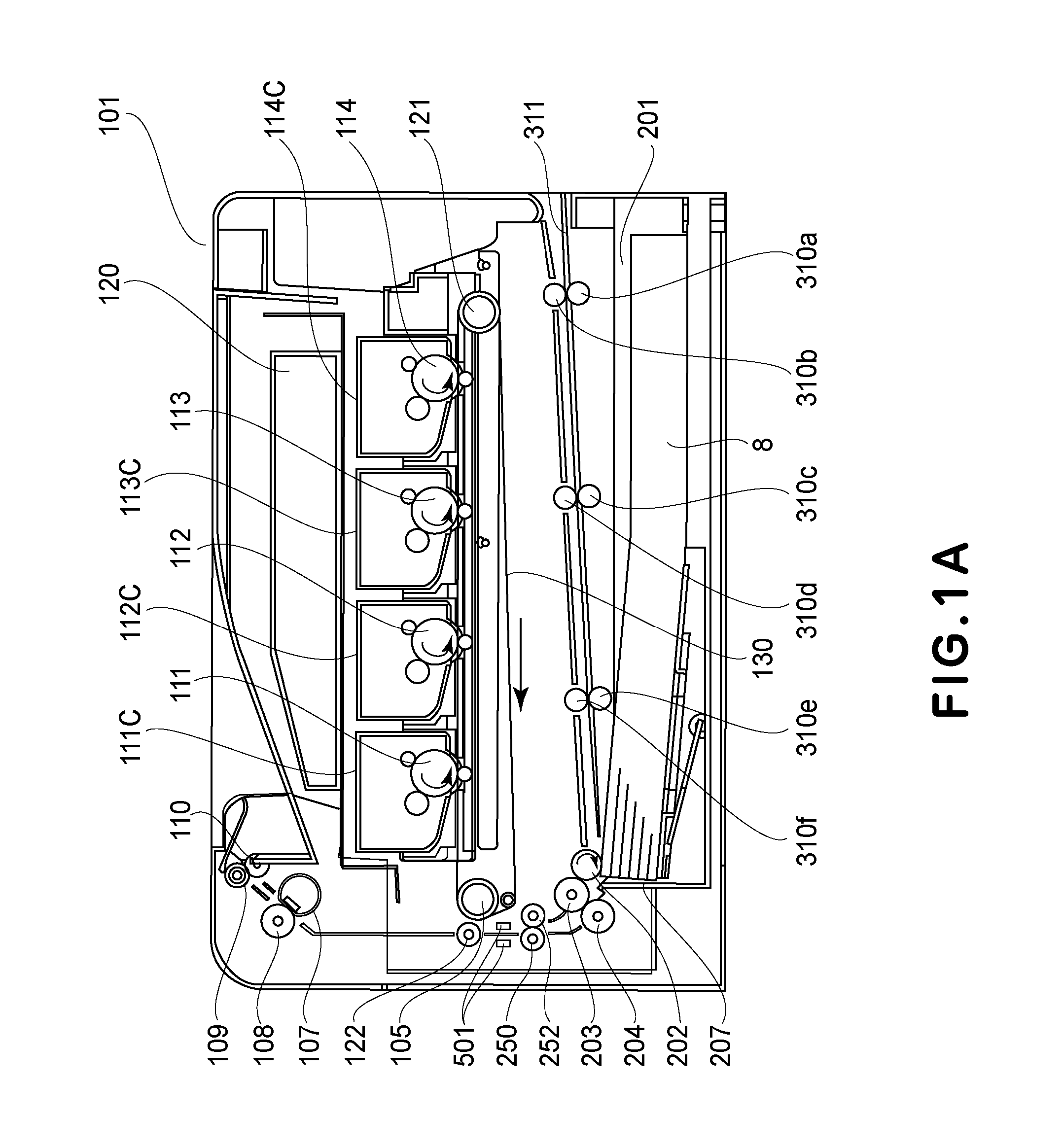
[0020]An outline of a general structure of an image forming apparatus in Embodiment 1 with reference to FIG. 1 will be described. In this embodiment, as the image forming apparatus, a laser beam printer 101 in which toner images of respective colors are successively transferred from photosensitive drums onto an intermediary transfer belt and thereafter are collectively transferred from the intermediary transfer belt onto a sheet as a recording material (medium) is used. Here, the sheet includes recording paper (thin paper, plain paper, thick paper), an OHP sheet and the like. In this embodiment, description will be made using the recording paper as an example. FIG. 1A is a schematic sectional view of the laser beam printer 101 (hereinafter also referred to as a main assembly 101). Sheets 8 stacked in a sheet feeding cassette 201 are fed one by one by a sheet feeding roller 202, rotating in an arrow direction (clockwise directio...

Example

Embodiment 2

Notification of Remaining Sheet Amount

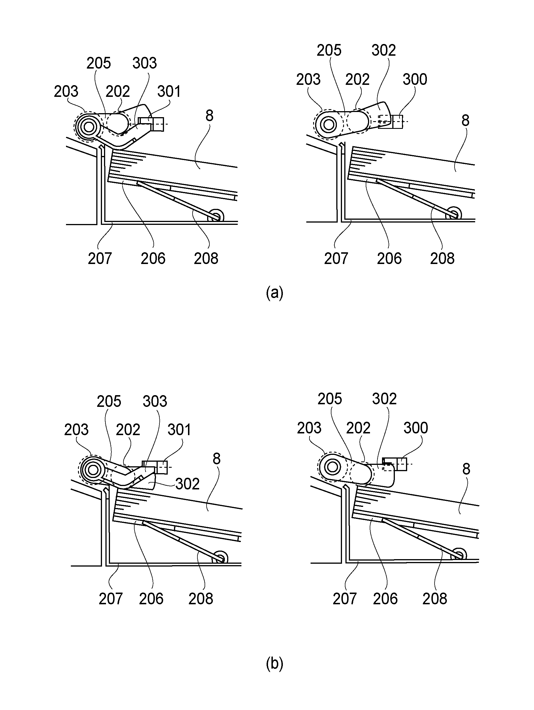
[0070]Of image forming apparatuses such as the image forming apparatus including the lift-up mechanism described in Embodiment 1, there is an image forming apparatus in which a remaining sheet amount of the sheet feeding cassette 201 is notified on the control panel 403 on the basis of the life-up amount of the sheet stacking member 206 when the sheet feeding cassette 201 is inserted. In such an image forming apparatus, in the case where the sheets are curled, the position of the uppermost surface of the sheets is raised, and therefore there is a problem such that the remaining sheet amount is notified as an amount larger than an actual stacking amount. In Embodiment 2, a method in which even in the state in which the sheets are curled, a remaining amount of the sheets 8 is accurately notified will be described.

[0071]In the image forming apparatus in this embodiment, similarly as in Embodiment 1, the initial lift-up (FIG. 5) is carri...

Example

Embodiment 3

[0080]In Embodiment 2, the method in which the degree of the curl of the sheets was detected during the sheet feeding operation and then the proper remaining sheet amount (unit: %) was notified was described. In Embodiment 3, a method in which the remaining sheet amount is notified with further high accuracy using a media sensor will be described. Incidentally, constituent elements which are the same as those in Embodiment 1 are represented by the same reference numerals or symbols and will be omitted from description.

[Constitution of Media Sensor]

[0081]A media sensor 501 as a third detecting portion is, as shown in FIG. 10, constituted by two light-emitting portions 502, 503 and a light-receiving portion 504. Light emitted from the light-emitting portion 502 is incident on the sheet 8 fed through the sheet feeding path along a feeding guide 505 with an angle of 45° with respect to the sheet 8 and is reflected by the sheet 8, and then is received as reflected light by th...


PUM


Abstract

A sheet feeding device includes a raising and lowering portion, a first detecting portion, a feeding portion, a second detecting portion, and a controller. When a change in a state of the feeding roller from a state of being in an uppermost sheet feedable position to a state of being not in the uppermost sheet feedable position is detected by the second detecting portion and then a change in a state of the uppermost sheet from a state of being in a feeding position to a state of being not in the feeding position is detected by the first detecting portion, the controller controls the raising and lowering portion to raise the stacking member on the basis of a correction amount determined based on a time from change timing of the second detecting portion to change timing of the first detecting portion.

Description

FIELD OF THE INVENTION AND RELATED ART[0001]The present invention relates to a sheet feeding device and an image forming apparatus and particularly relates to a position control of a sheet stacking member capable of raising and lowering.[0002]The image forming apparatus includes the sheet feeding device, in some cases, which includes a lifter mechanism for maintaining a height of an uppermost sheet of sheets stacked on the sheet stacking member at a substantially constant level and which feeds the sheet from the substantially constant height to an image forming portion by a feeding roller. The sheet feeding device includes a detecting sensor for detecting whether or not the sheet stacked on the sheet stacking member reaches a sheet feeding position, and on the basis of a detection result of the detecting sensor, raising and lowering of the sheet stacking member is controlled. By such control, the sheet feeding device is capable of maintaining the sheet feeding position at a substant...

Claims


Application Information

Patent Timeline
IPC IPC(8): B65H1/08B65H3/06G03G15/00B65H1/26B65H7/20B65H7/14B65H1/04B65H7/02
CPCB65H1/08B65H1/04B65H3/0684B65H7/02B65H2405/313B65H7/20B65H7/14G03G15/6529B65H1/266B65H1/18G03G15/6558G03G15/6511G03G2215/00396G03G2215/004G03G2215/0132B65H2405/11172B65H2407/21B65H2511/20B65H2511/30B65H2511/51B65H1/14B65H2220/01B65H2220/02B65H2220/03B65H2405/1117B65H2513/50
Inventor HIRAJIMA, MAREHIKO
Owner CANON KK
Why Eureka
Try Eureka