Seal structure and supercharger provided with the seal structure
- Summary
- Abstract
- Description
- Claims
- Application Information
AI Technical Summary
Benefits of technology
Problems solved by technology
Method used
Image

Examples
first embodiment
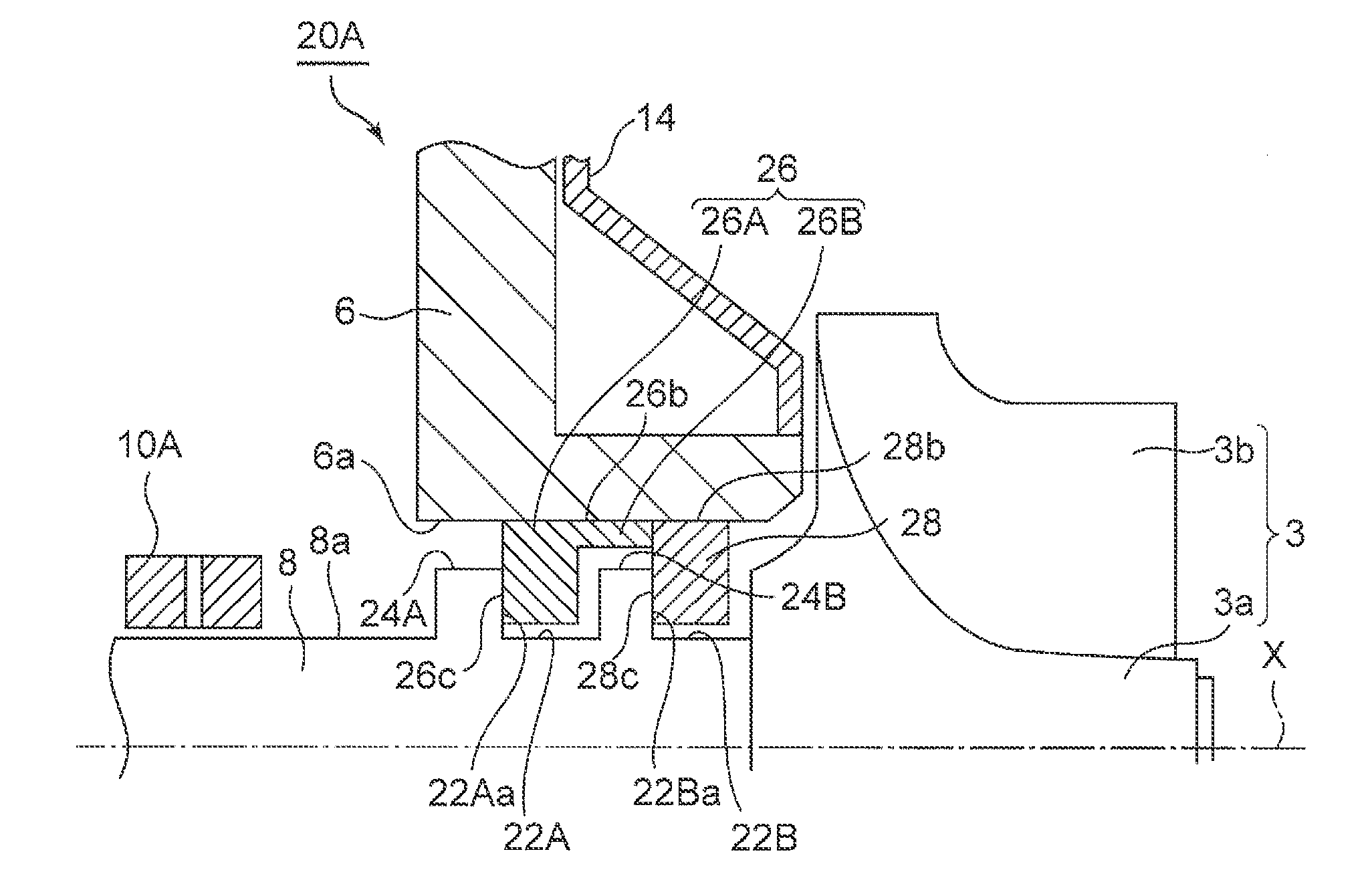
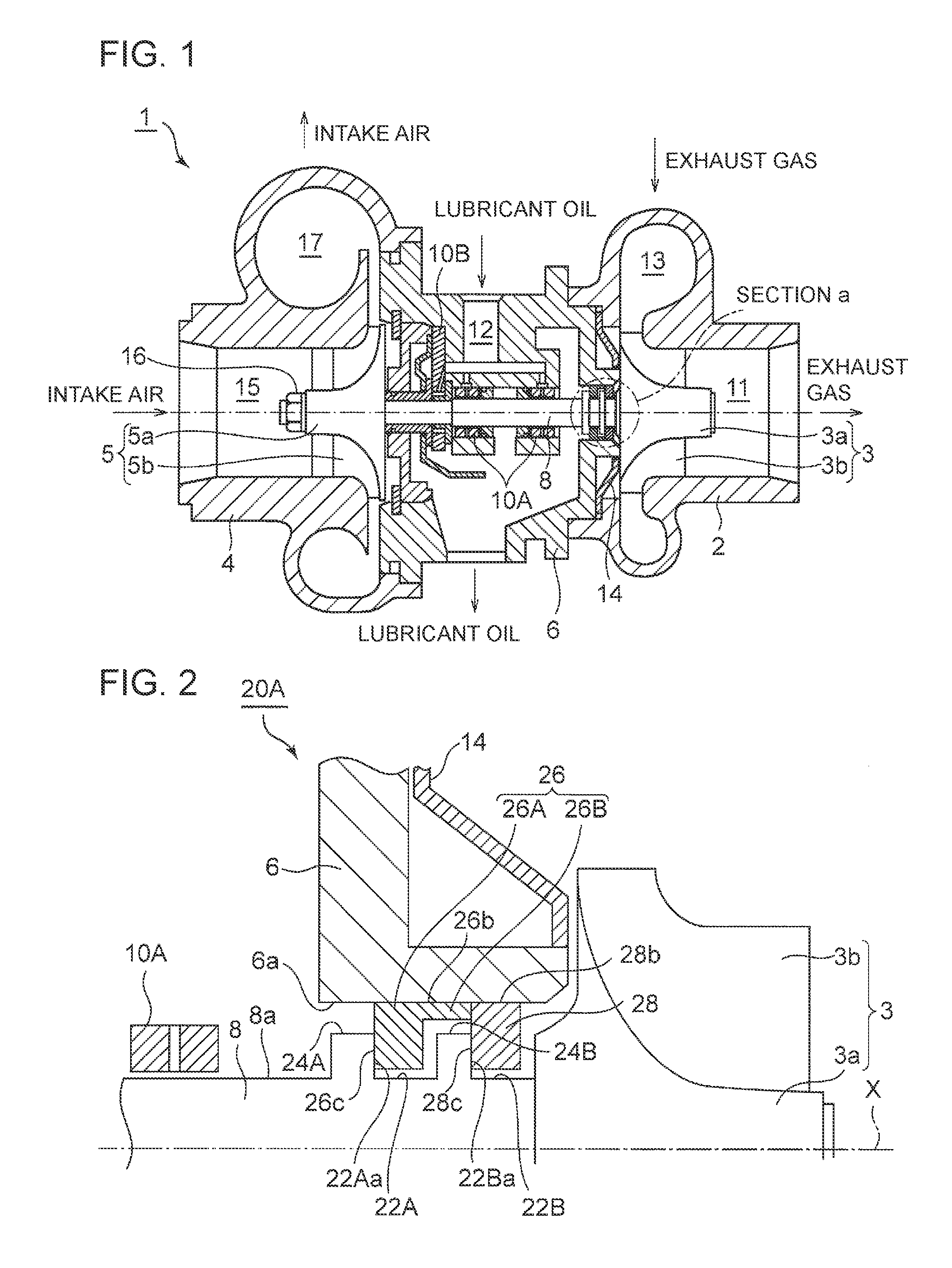
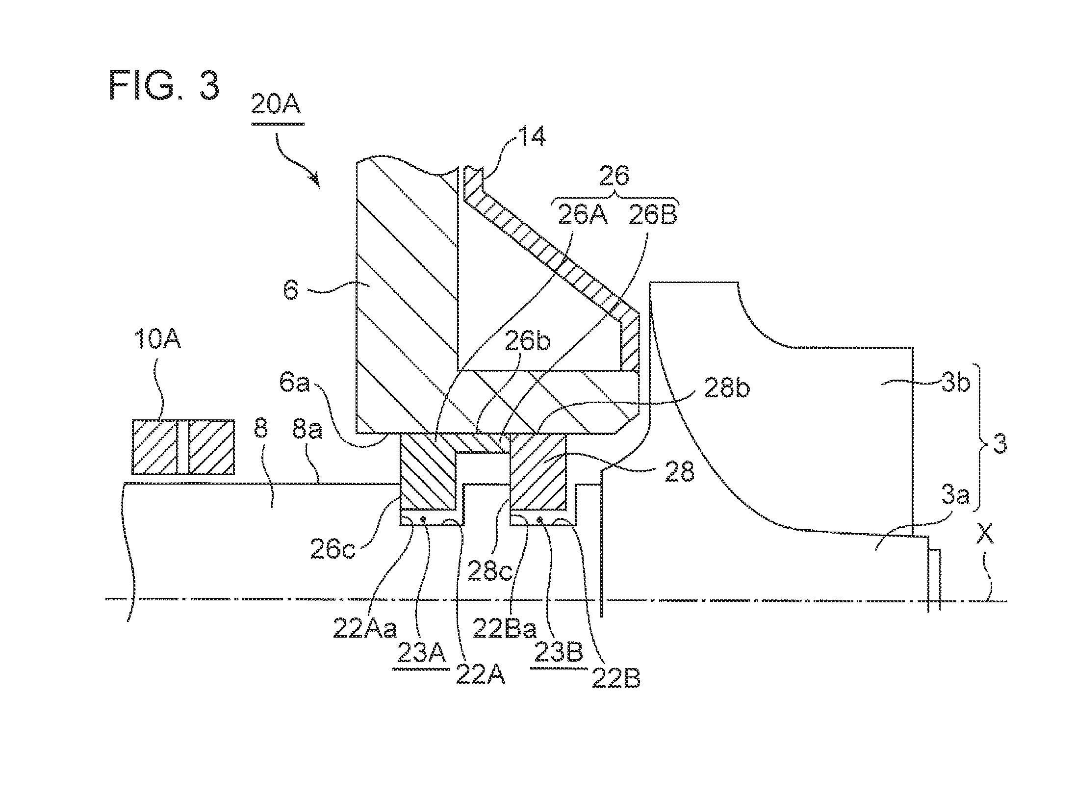
[0077]FIGS. 2 and 3 are enlarged views of section “a” in FIG. 1 and its peripheral structure, showing a cross-sectional view of a seal structure according to the first embodiment of the present invention.
[0078]As depicted in FIGS. 2 and 3, a seal structure 20A of the present embodiment includes the first seal groove 22A and the second seal groove 22B formed on the outer peripheral surface 8a of the rotary shaft 8, as well as the first seal ring 26 mounted to the first seal groove 22A and the second seal ring 28 mounted to the second seal groove 22B.
[0079]The first seal groove 22A and the second seal groove 22B are disposed between the turbine impeller 3 and the bearing 10A, with respect to the axial direction X of the rotary shaft 8. While the two seal grooves are provided, the first seal groove 22A is disposed on the side of the bearing 10A, and the second seal groove 22B is disposed on the side of the turbine impeller 3.
[0080]In the embodiment depicted in FIG. 2, the first project...
second embodiment
[0109]FIG. 9 is an enlarged view of section “a” in FIG. 1 and its peripheral structure, showing a cross-sectional view of a seal structure according to the second embodiment of the present invention.
[0110]A seal structure 20B of the present embodiment has some features similar to those of the seal structure 20A of the above-described first embodiment. Thus, the same components as those in the seal structure 20A of the first embodiment are associated with the same reference numerals and not described again in detail.
[0111]The first seal ring 26 of the present embodiment is different from that in the first embodiment in that there is no first-seal protruding portion 26B formed. The first seal ring 26 of the present embodiment includes only the first-seal body portion 26A corresponding to the seal ring 26 of the above described first embodiment.
[0112]Further, the inner peripheral surface 6a of the bearing housing 6 has a dent that faces the second seal groove 22B and constitutes a step...
third embodiment
[0127]FIG. 11 is an enlarged view of section “a” in FIG. 1 and its peripheral structure, showing a cross-sectional view of a seal structure according to the third embodiment of the present invention. FIGS. 12A and 12B are exploded perspective views showing another first seal ring and second seal ring according to the third embodiment of the present invention in a pre-assembly state.
[0128]A seal structure 20C of the present embodiment has some features similar to those of the seal structure 20A of the first embodiment and the seal structure 20B of the second embodiment described above. Thus, the same components as those in the seal structure 20A of the first embodiment and the seal structure 20B of the second embodiment are associated with the same reference numerals and not described in detail.
[0129]The first seal ring 26 of the present embodiment is different from that in the first embodiment in that there is no first-seal protruding portion 26B formed. The first seal ring 26 of th...
PUM
 Abstract
Description
Claims
Application Information
 - R&D
- Intellectual Property
- Life Sciences
- Materials
- Tech Scout
- Unparalleled Data Quality
- Higher Quality Content
- 60% Fewer Hallucinations
Browse by: Latest US Patents, China's latest patents, Technical Efficacy Thesaurus, Application Domain, Technology Topic, Popular Technical Reports.
© 2025 PatSnap. All rights reserved.Legal|Privacy policy|Modern Slavery Act Transparency Statement|Sitemap|About US| Contact US: help@patsnap.com