
Modular photoacoustic detection device

a detection device and module technology, applied in measurement devices, material analysis through optical means, sonic/ultrasonic/infrasonic waves, etc., can solve the problems of limited transmission wavelength, limited range of non-miniaturized laboratory equipment, and significant constraints on positioning and alignment of its elements for its production

Active Publication Date: 2016-12-08
COMMISSARIAT A LENERGIE ATOMIQUE ET AUX ENERGIES ALTERNATIVES
View PDF4 Cites 16 Cited by
  • Summary
  • Abstract
  • Description
  • Claims
  • Application Information

AI Technical Summary

Benefits of technology

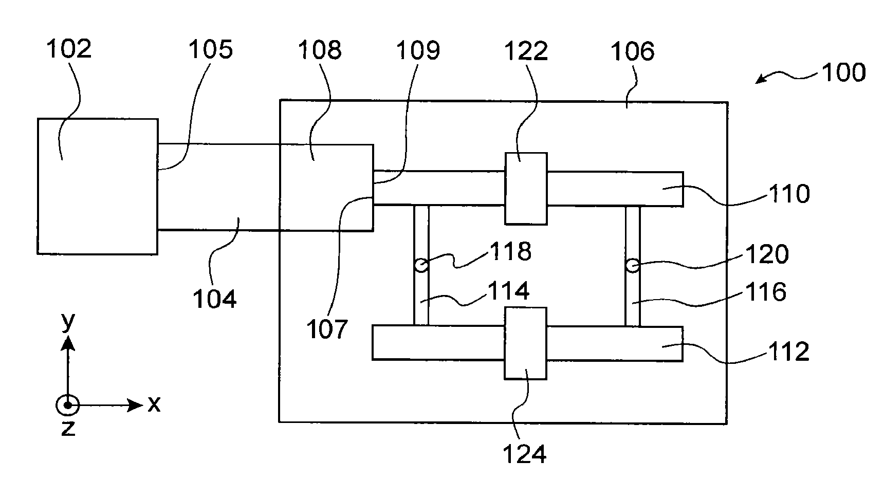
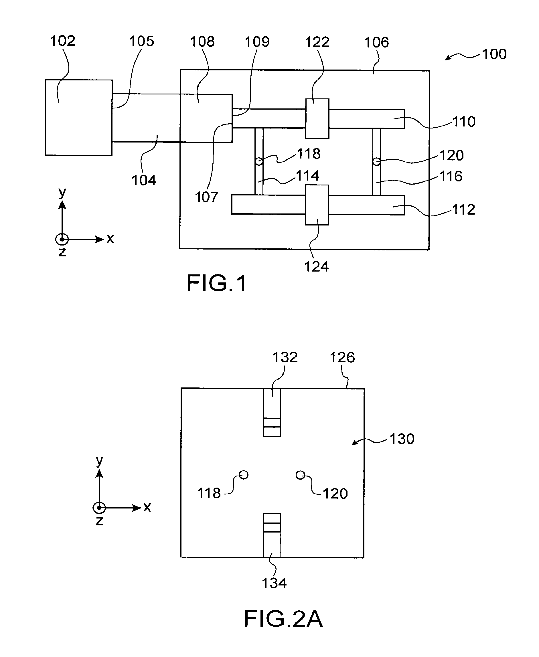
This patent is for a photoacoustic detection device that has a modular design, meaning that different parts can be easily replaced if one of them fails. This makes the device more robust and flexible because it allows for easier maintenance and replacement of faulty elements. Additionally, the device has a design that ensures better pressure homogeneity in the chambers where the detection occurs.

Problems solved by technology

Such a device nevertheless has the drawbacks of being limited to a non-miniaturized laboratory apparatus, of having limited transmission wavelengths, of being sensitive to temperature variations and to vibrations, and of having significant constraints of positioning and alignment of its elements for its production.
On the other hand, the monolithic structure of this device poses several drawbacks.
In fact, after one or more gas detections, the chambers of the photoacoustic cell may be contaminated by the gas or gases detected.
It is also possible that the microphones no longer work after several gas detections.
In addition, in order to be able to carry out the detection of different gases, the device necessarily makes use of several different laser sources, which represents a significant cost for the production of the detection device.
This is all the more problematic when the contamination of the chambers of the photoacoustic cell imposes the replacement of these different laser sources.

Method used


Image

  • Modular photoacoustic detection device
  • Modular photoacoustic detection device
  • Modular photoacoustic detection device

Examples


Embodiment Construction

[0012]An aim is thus to propose a photoacoustic detection device not posing the problems linked to monolithic detection devices of the prior art, that is to say not requiring a replacement of the whole of the detection device when the chambers of the photoacoustic cell are contaminated by gases, and which can serve in the detection of different gases without having to integrate necessarily different light sources in the device.

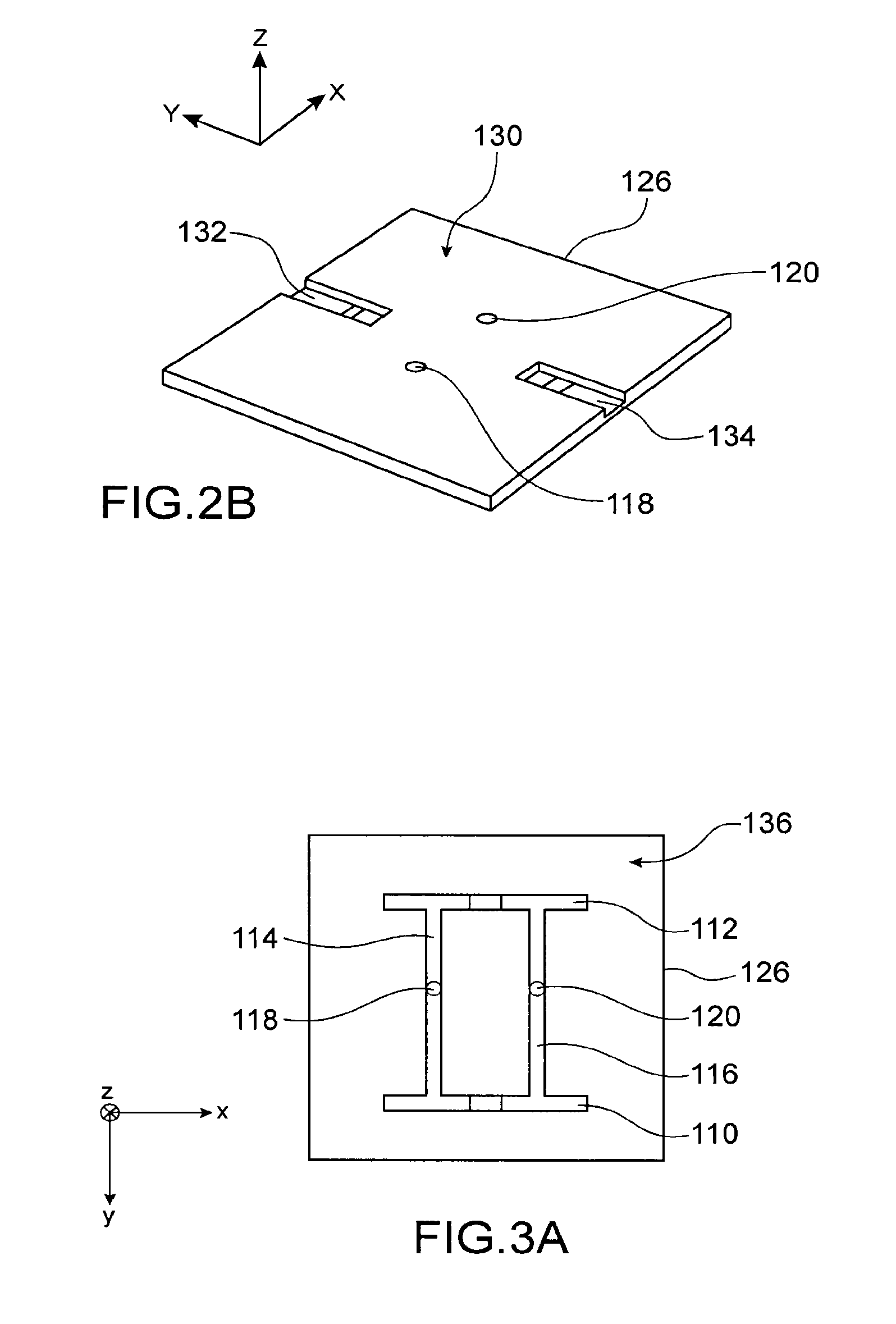
[0013]For this, a modular photoacoustic detection device is proposed comprising at least:[0014]a photoacoustic cell including at least two chambers connected by at least two capillaries and forming a Helmholtz type differential acoustic resonator;[0015]acoustic detectors coupled to the chambers;[0016]a light source capable of emitting a light beam having at least one wavelength capable of exciting a gas intended to be detected and which can be modulated to a resonance frequency of the photoacoustic cell;[0017]a first photonic circuit optically coupling the lig...


PUM


Abstract

Modular photoacoustic detection device comprising:a photoacoustic cell including at least two chambers connected by at least two capillaries and forming a Helmholtz type differential acoustic resonator;acoustic detectors coupled to the chambers;a light source capable of emitting a light beam having at least one wavelength capable of exciting a gas intended to be detected and which can be modulated to a resonance frequency of the photoacoustic cell;a first photonic circuit optically coupling the light source to an input face of a first of the chambers;wherein the first photonic circuit is arranged in a detachable manner in a first housing formed in the acoustic cell and emerging on the input face of the first chamber.

Description

TECHNICAL FIELD AND PRIOR ART[0001]The invention relates to the field of miniaturized photoacoustic detection devices, and notably that of miniaturized gas sensors making use of a photoacoustic effect for measuring the concentration of some gaseous elements.[0002]The principle of a measurement of a gas by photoacoustic effect is based on the excitation of an acoustic wave in the gas by a light source such as a pulsed or amplitude or wavelength modulated laser. The wavelength of the radiation, for example in the mid-infrared (MIR), the near-infrared (NIR), or the visible or UV domain, emitted by the laser is chosen to interact specifically with the molecules of the gas to detect. The emission of the light source being modulated, the energy absorbed by the gaseous molecules is restored in the form of a transitory heating which generates a pressure wave, itself measured by an acoustic detector such as a microphone. Although the photoacoustic effect has been known for a long time, its u...

Claims


Application Information

Patent Timeline
IPC IPC(8): G01N21/17
CPCG01N2021/1704G01N21/1702G01N29/2418G01N29/2425G01N2021/1708G01N2201/0245G01N2291/021G01N2291/02872
Inventor ROUXEL, JUSTINBRUN, MICKAELGLIERE, ALAINNICOLETTI, SERGIO
Owner COMMISSARIAT A LENERGIE ATOMIQUE ET AUX ENERGIES ALTERNATIVES
Learn More